Project 2: ULNAv2-C Datapath
This project is due on Wednesday, May 15, at 11:59:59 PM
(Eastern daylight time). You must use submit to
turn in your homework like so:
submit cs411_jtang proj2 proj2.circ proj2.S
Each submitted file must contain your name and assignment
number. For the Logisim file, place that information in a text label
on the main circuit. For the assembly file, place that information
in a comment at the top of the file.
This assignment builds upon the logic components from Homework 4, and your C code from Homework 3. Thus, you must have completed those homework assignments before attempting this assignment.
In this assignment, you will finish building the ULNAv2-C processor
in Logisim-evolution. To test your processor, you will translate
your uint16_mult() C code
from Homework 3 into
ULNAv2-C. Ideally your circuit implementation will match the
ULNAv2-C emulator's results.
Part 1: ULNAv2-C Floating Point Assembly
To begin, create a directory for your assignment and download the following files into that directory:
- http://www.csee.umbc.edu/~jtang/cs411.s24/homework/proj2/proj2.S
-
Skeleton assembly code. You will re-implement
your HW3's
uint16_mult()in ULNAv2-C. - http://www.csee.umbc.edu/~jtang/cs411.s24/homework/proj2/alutest.S
- Test code for your Part 2. You do not need to submit this with your assignment.
- http://www.csee.umbc.edu/~jtang/cs411.s24/homework/proj2/Makefile
- Builds all of the code for this assignment, by simply running make. Also included is a clean target to remove all built objects.
It is time to write the final assembly code. Take
your uint16_mult() function originally
written for HW3. Translate it into ULNAv2-C and insert it into
proj2.S. When your function is called,
registers R0 and R1 will have the
multiplicand and multiplier. Your code calculates the product and
stores that value back into R0.
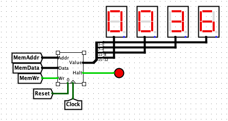
Assemble the binary. Test your binary in the ULNAv2-C emulator. Ensure your code calculates the sum 0x36 (decimal 54) for the inputs six and nine.
Part 2: Update ALU Selectors
In the previous two homework assignments, you analyzed ULNAv2-C instructions, to calculate Sum of Products for ALUOp, CondUpdate, and other signals. Examine ABus_selector. This subcircuit controls the ALU's "A Bus Input". Complete this circuit. For each instruction, decide what that instruction should set for ALUASrc. Then implement the A Bus Input via Instr_decoder and ABus_selector. (You are not required to draw Karnaugh maps, though they will help.)
Repeat this process for the ALU's "B Bus Input". Update Instr_decoder to calculate ALUBsrc, then finish implementing BBus_selector. Test your work using alutest.img. When your processor halts, compare your Register File's contents against the comment within the code file alutest.S.
Hint 1: ALUASrc and ALUBSrc only matter if the ALU is involved with an instruction. If the ALU is not involved, both of these signals are Don't Care.
Hint 2: You will need to add additional inputs into the muxes within ABus_selector and BBus_selector. The instructor's reference implementation had six choices for ALUASrc and seven choices for ALUBSrc.
Hint 3: The original Instr_decoder circuit
implemented ALUBSrc's ZeroExtend(imm8) to
handle just the movi instruction. You will likely need
to extend ZeroExtend(imm8) to cover other instructions.
Part 3: Implement Data Memory
Examine proj2_main. Observe how Data_Memory is a RAM device with a capacity of 64 KiB. It has three inputs and one output:
- MemAddr (16 bits, input)
- Controls which address to either store or load. Chosen by MemAddr_selector subcircuit.
- MemData (16 bits, input)
- Value to store into data memory. Ignored when not storing. Chosen by MemData_selector subcircuit.
- MemWr (1 bit, input)
- If true, write to memory (i.e., store a value).
- DataMemOut (16 bits, output)
- Value read from data memory at MemAddr.
Your Instr_decoder will need to generate these signals:
- MemAddrSrc (1 bit)
- Input to a mux within MemAddr_selector, to set MemAddr.
- MemDataSrc (1 bit)
- Input to a mux within MemData_selector, to set MemData.
- MemRead (1 bit)
- True when loading from memory, false when storing. This is a Don't Care when neither loading nor storing.
- MemToReg (1 bit)
- Controls which value to write into the Register File.
Then examine WIn_selector. Currently this circuit always routes ALUOut to WDataIn. Complete this circuit, by adding a mux. The mux selects from either ALUOut or DataMemOut, via the control signal MemToReg. Update Instr_decoder to calculate MemToReg.
Test your work so far, using memtest.img from HW4. If you did the above correctly, the CPU should still halt. Examine Data_Memory. You should see these values:
- Address
0x0032: value0x0032 - Address
0x0033: value0x0032 - Address
0xffff: value0x0002
R3 and R4 should
have the value 0x0032.
Hint 4: MemToReg is deceivingly easy to calculate. It should be true when loading from Data Memory, false when using the ALU, and Don't Care when RegWrite is false.
Hint 5: MemAddrSrc, MemDataSrc, and MemRead are also very simple to calculate.
Part 4: Add Branch Control Logic
In HW4, you started implementing Program_Control_Unit. Recall that BrReq was used to select between the current PC or PC+1. In this section, you will finish building the PCU. Study the ULNAv2-C RTN. Your Instr_decoder will need to generate these signals:
- BrReq (1 bit)
-
True if a branch shoud be taken. In HW4, you only needed to
handle
halt. Extend the calculation to cover all ULNAv2-C branching instructions. - BrType (3 bits)
- Multi-bit value that encodes the various branch types (unconditional, conditional branch if less than, conditional branch if not equal, etc.)
- ExtSel (2 bits)
-
Selects how to compute the new address. In HW4, there was only
one choice (PC, for just
halt). Other branch instructions have other target addresses.
Update Program_Control_Unit. This subcircuit must do two things:
- First decide if a branch should be taken or not. This requires mixing together BrReq, BrType, and CondCodes.
- If a branch should be taken, then decide what the new address should be. Observe how currently ExtSel selects a mux. Extend that mux's possible inputs using PC, IR, and reg_A.
Hint 6: Next_PC should be set to PC+1 when both BrReq is true, but BrType is a conditional branch that should not be taken according to CondCodes.
Hint 7: Ensure that your circuit still
implements halt, otherwise grading will be very
difficult.
Test your decoder thus far with adder.S
and bosrt.S from Homework 4. Load the assembled image into
Instruction_Memory, then poke the clock several times. Check that
all signals are generated correctly, and that the program goes into
an infinite loop when it executes the halt
instruction. Compare your circuit's state to what the emulator
reports.
Then load your proj2.S binary, from Part 1, into Instruction_Memory. Enable the clock. After the system halts, compare Data_Memory with the comments at the top of proj2.S. If you get the same results, you most likely will score very well for this project!
Other Hints and Notes
- Ask plenty of questions on the Blackboard discussion board.
- At the top of your proj2.S, list any help you received as well as web pages you consulted. Please do not use any URL shorteners, such as goo.gl or TinyURL. Also, do not cite shared data services, such as Pastebin, Dropbox, or Google Drive.
- You may use any Logisim component that you can find. If you use a component that does not natively come with Logisim, be sure you cite it.
Extra Credit
You may earn an additional 5% credit for this assignment by making
this assignment easier to grade. As currently written, the grader
must manually inspect Data_Memory when grading Part 1. Create a new
subcircuit, Proj2_EC. This subcircuit snoops upon all
writes to data memory. If it detects a write to
address 0xfffe, it stores the written value into an
internal register. It also snoops upon writes
to 0xffff, to indicate when the processor halts. It
outputs the internal register and when
0xffff is being written, like so:
If you choose to perform this extra credit, put a comment near the top of your proj2.S, alerting the grader.