Homework 3: Complex Arithmetic
This homework is due on Wednesday, April 10, at 11:59:59 PM
(Eastern daylight time). You must use submit to
turn in your homework like so:
submit cs411_jtang hw3 hw3.c hw3.circ hw3.txt [image1...]
The grader will use the supplied Makefile to compile your
work. In addition, each submitted source code file must have a file
header comment, as described on the coding
conventions page. For the Logisim file, place your name and
assignment number in a text label on the main circuit. For image
files, ensure your name and assignment number appear somewhere in
the image.
You can only complete this assignment within an ARMv8-A development environment, and thus you must have completed the first homework before attempting this assignment. In addition, you must have a working 16-bit ALU from the first project.
Back in the good ol' days, computers were built to perform only integer arithmetic, as that CPUs lacked support for floating point calculations. For example, the original Intel systems deferred floating point to an optional coprocessor, the Intel 8087 chip. Furthermore, integer multiplication and integer division were implemented by the coprocessor, not the main CPU. For users that did not have an Intel 8087, they relied upon specialized libraries to implement floating point and advanced arithmetic operations purely in software. These became known as soft floating point systems.
In this assignment, you will implement a subset of a floating point library. Specifically, you will write in code to perform floating point multiplication. You will then continue implementing parts of the ULNAv2-C processor.
Part 1: Unsigned Integer Multiplication
To begin, create a directory for your assignment and download the following files into that directory:
- http://www.csee.umbc.edu/~jtang/cs411.s24/homework/hw3/hw3.c
- Skeleton code for this assignment.
- http://www.csee.umbc.edu/~jtang/cs411.s24/homework/hw3/hw3.circ
- Additional circuitry for your ULNAv2-C processor.
- http://www.csee.umbc.edu/~jtang/cs411.s24/homework/hw3/Makefile
- Builds the code for this assignment, by simply running make. Also included is a clean target to remove all built objects. You do not need to modify this file, nor should you submit it with your work.
Now run make to compile hw3.c. The program takes two integer parameters. The given skeleton code converts those parameters into two 16-bit values.
Your first job is to implement uint16_mult(). Read the
function comments in hw3.c. Implement a multiplication
algorithm of your choice. Note that you are
performing 16-bit unsigned integer multiplication;
therefore the product will be 32-bits. Sample output is at the
bottom of this assignment.
Restriction 1: You may not use the built-in multiplication, division, nor modulo division instructions for this assignment. That would be cheating, wouldn't it? You are limited to only adds, subtracts, shifts, rotates, bitmasks, bitwise logic, compares, and branches.
In the final project, you will translate your Part 1 code into assembly. It is in your best interest to write the code cleanly, with plenty of comments. Although not required, you should strive to write this function to execute in constant time, regardless of input parameters.
Part 2: Floating Point Multiplication
The next task is to
implement is_half_float_normal(). Read the function
comments in hw3.c. Your function takes in a 16-bit
value. Treat that value as
an IEEE-753
half-floating point value. Determine if the value is normal or
not (either denormal, zero, infinity, or Not a
Number). Return true if it is
normal, false otherwise.
Next, implement half_float_mult(), as per its function
comments. This function takes as input two 16-bit values,
representing normal half-floating point values. You are to calculate
their half-floating point product. You may assume the resulting
value will also be a normal half-floating point value.
Restriction 2: Like with Part 1, your code may not
use real multiplication. Instead, you must use
your uint16_mult() function to calculate the
significand.
The sign bit and exponent bits are easy to calculate. Determining
the significand bits is harder. Don't forget to add the implied
leading 1 to the 10-bit significands, when
calling uint16_mult(). Because you are multiplying two
11-bit values, the result is a 22-bit value: 2 bits to the left of
the decimal point, and 20 bits to the right. You need to
re-normalize this value like so:
- If the top-most bit (bit 21) is a 1, then shift everything to the right and increment the exponent.
- Otherwise as long as bit 20 is a 0, shift everything to the left and decrement the exponent.
Note that real hardware will round up the least significant bit, if the input integer cannot be stored as a half floating point. You are not required to do so.
Compile your code. Run hw3, passing in two normal values. The provided code will display both the correct product and your result.
Part 3: ULNAv2-C Register File
As a reminder, the first project introduced the ULNAv2-C instruction set. Use the following links to obtain the full instruction set:
There are 8 general purpose registers, each 16-bit wide, referred to
as R0 through R7. There is also a 16-bit
program counter (PC) register. All registers are initialized to 0
after reset.
All instructions are 16 bits. The top 5 bits (towards MSB) give the instruction number. Instruction numbers 0 through 7 are class A; 8 through 15 are class B, and so forth. In other words, the top two bits (bits 15 and 14) specify the instruction class. The bottom 11 bits (bits 10 to) 0 specify operands.
| Instruction Class | 15 | 14 | 13 | 12 | 11 | 10 | 9 | 8 | 7 | 6 | 5 | 4 | 3 | 2 | 1 | 0 |
|---|---|---|---|---|---|---|---|---|---|---|---|---|---|---|---|---|
| A | 0 | 0 | subtype | Reg W | Reg A | Reg B | X | X | ||||||||
| B | 0 | 1 | subtype | Reg W | Reg A | Imm 5 | ||||||||||
| C | 1 | 0 | subtype | Reg W | Imm 8 | |||||||||||
| D | 1 | 1 | subtype | Imm 11 | ||||||||||||
Here are further details for some of the instructions:
-
and., andi., or., ori. - These instructions update the condition codes Z and N based upon the result of the logic operation. The condition codes C and V are set to Don't Cares; Z and N are based upon the result of the operation.
-
ash - This normally performs an arithmetic shift right, by a number of bit positions equal to the immediate, towards the LSB. If the immediate's MSB is set (i.e., bit 4), shift left instead.
-
br -
The
BandWregister values are Don't Cares. -
brl -
This "branch to register and link" instruction first
copies the program counter to a register, before jumping to the
address within a register.
WandAcan refer to the same register, in which case the PC is first saved prior to the jump. -
cmp., cmpi. - These instruction do not modify any registers nor data memory. They simply set the ALU's condition codes.
-
halt - The immediate value is first sign-extended to 16 bits, and then that value is written to data memory at address 0xFFFF. It then explicitly sets the PC to itself, preventing the program from executing further.
-
lsh - This normally performs a logical shift right, by a number of bit positions equal to the immediate, towards the LSB. If the immediate's MSB is set (i.e., bit 4), then shift left instead.
-
movi - This replaces a register with the 8-bit immediate value. The upper eight bits are set to zero.
-
movis - This replaces the upper eight bits of a register with the 8-bit immediate value. (This instruction moves an immediate that has been shifted to the left by eight bit positions.) The lower eight bits remain unmodified.
-
rot - This normally rolls a register's value to the right, by a number of bit positions equal to the immediate, towards the LSB. If the immediate's MSB is set (i.e., bit 4), then rotate left instead.
Open both proj1.circ and hw3.circ. From your proj1.circ, copy your implementation of adder_2bit, adder_4bit, and ALU into hw3.circ.
Do not link hw3.circ to proj1.circ. Doing so will result in grading penalties.
Implement the subcircuit register_file_8x16bit. This register file must hold eight 16-bit registers. It has these seven inputs:
- ASel (3 bits)
- Selects a register to route out through ADataOut.
- BSel (3 bits)
- Selects a register to route out through BDataOut.
- WSel (3 bits)
- Selects a register to route out through WDataOut, and also which register to update.
- WrEnable (1 bit)
- If true and Clock is true, then update the register specified by WSel.
- WDataIn (16 bits)
- Value to store into the register file, when WrEnable and Clock are true.
- Reset (1 bit)
- Reset line. If true, unconditionally reset all register values to zero.
- Clock (1 bit)
- If true and WrEnable is true, then update the register specified by WSel using the value at WDataIn.
For ease of grading, identify your registers, like so:
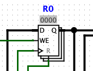
Caution: The register file is only to be updated when both WrEnable and Clock are true. Many previous students connected Clock to both the register's enable and clock ports. This is incorrect. Clockonly connects to registers' clock ports.
Part 4: Karnaugh Maps for ALU Operations
You will now start assembling ULNAv2-C's single-cycle datapath. Examine main. Observe how IR is the instruction register; it holds an ULNAv2-C 16-bit instruction. That instruction is passed into ULNAv2c_decoder, to extract out the five-bit instruction number (abbreviated Instr). Instr is then passed into Instr_decoder for further processing.
Analyze ULNAv2-C's instruction set. All Class A, B, and C
instructions (i.e., instruction numbers zero through 23) are to use
the ALU for their execution. Some of the implementations will be
obvious. Take a look at instruction number
zero, or:
R[W] ← R[A] OR R[B]
When executing this instruction, the ALU's A Bus should be set to R[A], B Bus set to R[B], and the operation set to 2 (corresponding to logical or).
Here are two instructions with less obvious
implementations. Both movi and movis set
register R[W] based upon immediate
values. movi could be implemented in at least four
different ways:
| A Bus Input | B Bus Input | Operation |
|---|---|---|
| Constant zero | Zero Extended imm8 | addition |
| Zero Extended imm8 | Constant zero | subtraction |
| Constant zero | Zero Extended imm8 | logical or |
| Zero Extended imm8 | Zero Extended imm8 | logical and |
movis, we will set A Bus
to R[W][7:0], B Bus to imm8, shifted left by 8,
and operation also to logical or.
Create a text file hw3.txt. In this file, list all Class A, B, and C instructions, excluding the three undefined instructions. For each instruction, decide which value should be used for A Bus, B Bus, and ALU Operation.
Hint 1: Your ALU implements 7 different ALU operations. All of these ULNAv2-C instructions are executable using the ALU.
Hint 2: As much as you can, try to use similar inputs as possible. The instructor's reference implementation had six different A Bus inputs, and seven different B Bus inputs. Look at the subcircuits ABus_selector and BBus_selector for ideas.
Hint 3: The A Bus input should be derived from R[A], R[W], or a constant number. The B Bus input should be derived from R[B], an immediate value, or a constant number. Some instructions require the Program Counter as an input. The instructor's reference implementation routed the PC into A Bus; other implementations may route PC through the B Bus.
After deciding which inputs to use, construct Karnaugh
Maps for the ALU Operation. Each map has 5 inputs, corresponding to
the instruction number. Calculate a sum of product for each of the
seven ALU Operations. For consistency in grading, the MSB is
input E, while LSB is input A. For
example, movis's instruction would be encoded as
this:
ABCDE
Add to your hw3.txt the Sum of Products. Alternatively, draw your K-Maps and Sum of Products on a piece of paper, take a snapshot of the page, then upload the image with the rest of your assignment.
Part 5: Decode ALU Operations
Now that you have calculated Sum of Products, return to hw3.circ. Examine both ABus_selector and BBus_selector. These subcircuits control the inputs into the ALU. You do not need to modify them for this assignment.
Then look at Instr_decoder. This takes as input the 5-bit
instruction number. Among other things, it calculates the inputs for
the ALU. As a demonstration, it implements movi
and movis selections for A Bus and B Bus.
Using your Sum of Products from Part 4, calculate the ALU Operations value. In other words, given an arbitrary 5-bit instruction number, calculate the ALUOp signal. For undefined instructions and Class D instructions, ALUOp is a Don't Care. Test your implementation using the below sample values.
Sample Output
Here is a sample output from running hw3. The grader will use different values to test your submission.
$ ./hw3 0x441c 0x4436
Part 1:
  unsigned integer multiply 0x441C and 0x4436:
    correct result: 0X1225CDE8
    your result:    0X1225CDE8
Part 2:
  0x441c is normal
  0x4436 is normal
  half-float multiply 4.10938 and 4.21094:
    correct result: 0x4C53
    your result:    0x4C53
Test your Instr_decoder like so:
-
In main, set IR to
a011. This encodes the instructionmovi r0, #11. - Pulse the clock line a full cycle (i.e., poke it twice).
- Examine your register file. Your R0 should now have the value 0x0011.
-
Return to hw3_main. Set IR
to
b004. This encodesmovis r0, #4. - Pulse the clock another cycle. Your R0 register should now have the value 0x0411.
-
Execute three more instructions:
a121(movi r1, #21)b104(movis r1, #4)0a20(add. r2, r1, r0)
- If everything worked, R0 should hold 0x0411, R1 should hold 0x0421, and R2 should hold 0x0832.
Other Hints and Notes
- Ask plenty of questions on the Blackboard discussion board.
- At the top of your submitted files, list any help you received as well as web pages you consulted. Please do not use any URL shorteners, such as goo.gl or TinyURL. Also, do not cite shared data services, such as Pastebin, Dropbox, or Google Drive.
- C99 introduced fixed-width integer types. This assignment intentionally uses them, to force the compiler to use certain register assignments.
- Within hw3.circ, you may move input and output ports. However, please do not rename the ports, as that will make grading much more difficult.
- You will reuse hw3.circ for the remainder of this semester. You will finish filling in all of the other subcircuits within.
Extra Credit
Sorry, there is no extra credit available for this assignment.