Homework 4: Introducing ULNAv2-B
This homework is due on Wednesday, April 26, at 11:59:59 PM
(Eastern daylight time). You must use submit to
turn in your homework like so:
submit cs411_jtang hw4 hw4.c multu8.S hw4.circ [...]
The grader will use the supplied Makefile to compile your
work. In addition, each submitted source code file must have a file
header comment, as described on the coding
conventions page. For the Logisim file, place your name and
assignment number in a text label on the main circuit.
This assignment builds upon the logic components you created in the third homework, and thus you must have completed that homework before attempting this assignment. Furthermore, you must have a working unsigned multiplication algorithm written in assembly.
In this assignment, you will implement a disassembler, in C, for the ULNAv2-B instruction set. You will then use that disassembler to partially decode a ULNAv2-B program, displaying control signals that would be generated for each instruction. Finally, you will add a decoder into your Logisim file to decode those control signals.
Part 0.1: ULNAv2-B Instruction Set
ULNAv2-B (UMBC's Limited Nifty Architecture, version 2 bugfix B) is the 16-bit RISC architecture that you will implement for this class's final project. In ULNAv2-B, all instructions are 16 bits and all data registers hold 16 bits. Internally all values are stored as big-endian.
There are 8 general purpose registers, each 16-bit wide, referred to
as R0 through R7. There is also a 16-bit
program counter (PC) register. All registers are initialized to 0
after reset.
ULNAv2-B has separate Instruction Memory and Data Memory systems (i.e., a Harvard architecture). Both memories have 16-bit addresses and 16-bit data widths. The data memory contents are initialized at zero at processor startup and is writable, while instruction memory is preloaded with the program to execute and is considered read-only.
All instructions are 16 bits. The top 5 bits (towards MSB) give the instruction number, such that the top 2 bits (bits 15 and 14) specify the instruction class, the next three bits are instruction subtype. All remaining bits specify operands.
| Instruction Class | 15 | 14 | 13 | 12 | 11 | 10 | 9 | 8 | 7 | 6 | 5 | 4 | 3 | 2 | 1 | 0 |
|---|---|---|---|---|---|---|---|---|---|---|---|---|---|---|---|---|
| A | 0 | 0 | subtype | Reg W | Reg A | Reg B | X | X | ||||||||
| B | 0 | 1 | subtype | Reg W | Reg A | Imm 5 | ||||||||||
| C | 1 | 0 | subtype | Reg W | Imm 8 | |||||||||||
| D | 1 | 1 | subtype | Imm 11 | ||||||||||||
There are 29 instructions defined in ULNAv2-B. Instructions numbers 6, 17, and 19 are undefined. Use the following links to obtain the full instruction set:
In ULNAv2-B RTN, the notation R[n] means general
purpose register n. MemWord[n] means the
16-bit value within data memory at address n. All
additions and subtractions treat operands as two's complement signed
integer values. When executed, only some of these instructions
update the ALU's condition codes Z, C, N,
and V, as specified by the column Updates Cond
Codes; these instructions' names also end with a dot as a
mnemonic.
Here are further details for some of the instructions:
-
and., andi., or., ori. - These instructions update the condition codes Z and N based upon the result of the logic operation. The condition codes C and V are set to Don't Cares; Z and N are based upon the result of the operation.
-
ash - This normally performs an arithmetic shift right, by a number of bit positions equal to the immediate, towards the LSB. If the immediate is negative, then shift left instead.
-
br -
The
BandWregister values are Don't Cares. -
brl -
This "branch to register and link" instruction first
copies the program counter to a register, before jumping to the
address within a register.
WandAcan refer to the same register, in which case the PC is first saved prior to the jump. -
cmp., cmpi. - These instruction do not modify any registers nor data memory. They simply set the ALU's condition codes.
-
halt - The immediate value is first sign-extended to 16 bits, and then that value is written to data memory at address 0xFFFF. It then explicitly sets the PC to itself, preventing the program from executing further.
-
lsh - This normally performs a logical shift right, by a number of bit positions equal to the immediate, towards the LSB. If the immediate is negative, then shift left instead.
-
movis - This replaces the upper eight bits of a register with the 8-bit immediate value. (This instruction moves an immediate that has been shifted to the left by eight bit positions.) The lower eight bits remain unmodified.
-
rot - This normally rolls a register's value to the right, by a number of bit positions equal to the immediate, towards the LSB. If the immediate is negative, then rotate left instead.
Study ULNAv2-B carefully. Post on the Blackboard forum questions you have about this instruction set.
Part 0.2: ULNAv2-B Assembler and Emulator
Your friendly instructor has written several useful ULNAv2-B tools. Create in your home directory a subdirectory named ulnav2-b, add then fetch the following files via wget:
- http://www.csee.umbc.edu/~jtang/cs411.s23/homework/ulnav2-b/ulnav2-b-as.c
- Assembler for ULNAv2-B.
- http://www.csee.umbc.edu/~jtang/cs411.s23/homework/ulnav2-b/ulnav2-b-as.h
- Common header file used by the assembler.
- http://www.csee.umbc.edu/~jtang/cs411.s23/homework/ulnav2-b/ulnav2-b-lexer.l
- Flex file that "tokenizes" an input stream.
- http://www.csee.umbc.edu/~jtang/cs411.s23/homework/ulnav2-b/ulnav2-b-parser.y
- Bison file that parses tokens into an "abstract syntax tree".
- http://www.csee.umbc.edu/~jtang/cs411.s23/homework/ulnav2-b/ulnav2-b-emu.cpp
- Software emulator for the ULNAv2-B instruction set, controllable using a GDB-like interface.
- http://www.csee.umbc.edu/~jtang/cs411.s23/homework/ulnav2-b/Makefile
- Builds the above tools, by simply running make. Also included is a clean target to remove all built objects.
In addition, you need to install the flex and bison utilities. For a Linux development host, run the following:
sudo apt-get install flex bison libreadline-dev
After you have downloaded all of the files, run make. You will use the resulting tools ulnav2-b-as and ulnav2-b-emu for both this assignment and the final project. You may find these files interesting to read through, if you are interested in compiler theory.
Part 0.3: ULNAv2-B Procedure Convention
Similar to ARMv8-A's Procedure Call Standard, ULNAv2-B has the following calling convention:
| Register | Usage | Who Responsible? |
|---|---|---|
| R0 | First parameter into function, and holds return value from function | Caller |
| R1 | Second parameter into function | Caller |
| R2 through R5 | Temporary storage | Callee |
| R6 | Stack Pointer | Callee |
| R7 | Link Register | Callee |
When an assembly function is called, R0 will hold the
first function parameter while R1 holds the second
parameter. The function's return value is stored at
R0, and it jumps to the address in R7 to
return to the caller. If the function needs to write to
registers R2 through R5, or if it needs to
call a subfunction (and therefore change R7), do the
following:
-
Decrement the stack pointer (i.e., update
R6). Then preserve registers on the stack (i.e., by usingstwiinstruction). -
If the function needs to call a subfunction, copy the link
register (i.e.,
R7) to the stack. SetR0andR1to the subfunction's parameters. Then call the subfunction withbl. -
Prior to returning from the function,
br, restore the stack pointer (i.e., updateR6) to what it was when the function first began. Then uncoditionally jump to the return address (i.e.,br R7).
Part 1: ULNAv2-B Disassembler
Create another directory for this assignment. Download the following additional files via wget:
- http://www.csee.umbc.edu/~jtang/cs411.s23/homework/hw4/hw4.c
- Skeleton C code for this assignment.
- http://www.csee.umbc.edu/~jtang/cs411.s23/homework/hw4/multu8.S
- Skeleton assembly code for this assignment.
- http://www.csee.umbc.edu/~jtang/cs411.s23/homework/hw4/adder.S
- Demonstration ULNAv2-B program, that adds two values and stores the result into data memory. Do not submit this file with your work.
- http://www.csee.umbc.edu/~jtang/cs411.s23/homework/hw4/bsort.S
- Another demonstration ULNAv2-B program, that bubble sorts an array of 4 values. Do not submit this file with your work.
- http://www.csee.umbc.edu/~jtang/cs411.s23/homework/hw4/Makefile
- Builds all of the code for this assignment, by simply running make. Also included is a clean target to remove all built objects.
Now run make to build the disassembler and demonstration ULNAv2-B programs. Examine the files adder.S and bsort.S. The ULNAv2-B assembly syntax is similar to ARMv8-A syntax. The minor differences between ULNAv2-B and ARMv8-A syntax are:
-
Like ARMv8-A, immediate values must be preceded
by
#, but in ULNAv2-B it is optional. The value after the#may be prefixed by0xto indicate a hexadecimal value. Otherwise it is treated as a decimal. - Unlike ARMv8-A, ULNAv2-B does not support pre-indexed nor post-indexed addressing modes.
-
Whereas ARMv8-A can refer to the same register using
an
XorWnotation, all ULNAv2-B registers are always 16-bits, and are always referenced by anR.
Now examine the generated files adder.img and bsort.img. These are Logisim memory image files. Every line after the first represents a 16-bit value to be stored in instructional memory. When ulnav2-b-as is run with the -g flag, additional debugging information are added as comments.
Returning to this homework, the first part of this assignment
involves building your ULNAv2-B
Disassembler. Run hw4, passing in an image filename on
the command line. For each instruction within the image file, the
disassembler displays the raw 16-bit value and its instruction
class. You are to further decode the instruction. Based upon the
instruction number, display the instruction name. For example, given
the instruction c7ee, which is a branch instruction,
display this:
    c7ee: instruction class "D"
          this is: b
Part 2: Control Signals
In the final project, you will use Logisim to implement ULNAv2-B as a single-cycle datapath. This will take a while to do. In preparation, your next task is to analyze the ULNAv2-B instruction set and determine how to set these control signals:
-
CondUpdate(1 bit) - This signal is 1 if the Condition Codes register should be modified.
-
MemRead(1 bit) - This signal is 1 when reading from data memory.
-
MemWrite(1 bit) - This signal is 1 when writing to data memory.
-
RegWrite(1 bit) - This signal is 1 when the register file should be written with the contents of the W Bus.
Start with the editable ULNAv2-B spreadsheet. Add columns to the
table, corresponding to each of the above control signals. Then for
each instruction, determine if that instruction should set the
control signal to a zero or one. For the three undefined
instructions, set their control signals to
zero. CondUpdate is already given for you.
Next, calculate the Sum of Products for all four control signals,
using your favorite algorithm of choice. Then in hw4.c,
implement the
functions signal_condupdate(), signal_memread(), signal_memwrite(),
and signal_regwrite(). These four functions are to
return true if the given instruction should set that
signal or not. Recompile hw4.c, then test that your program
decodes instructions to generate correct control signals.
Note: Your final implementation of ULNAv2-B will require many more signals. For this homework, you only need to generate the above signals.
Part 3: Implement Unsigned Multiplication Function
In this next part, you will write your own ULNAv2-B assembly function. Examine the skeleton file multu8.S. This assembly code is to implement unsigned 8-bit integer multiplication, based upon your code you wrote in HW3. The difference is that this time the inputs are 8-bits, and your product is at 16 bits. As per the ULNAv8-B calling convention described in Part 0.3,
-
Registers
R0andR1hold the function's parameters. -
Register
R7has the return value. -
If your function uses registers
R2throughR5, be sure to store their previous values to the stack (R6), then restore their values prior to returning from the function.
Run make to assemble your code into the image file multu8.img. In the final project, you will execute that image within Logisim. For this assignment, you will instead execute the image using the ULNAv2-B emulator ulnav2-b-emu. Start the emulator like so:
$ ~/ulnav2-b/ulnav2-b-emu multu8.img
The emulator takes you to a command prompt. Enter ? to
view a list of commands. You can simulate one CPU cycle at a time by
entering s, or run continuously until a halt
instruction with the command c.
Note: the grader will use different values
for R0 and R1 during grading.
Part 4: Instruction Decoder
In this part of the assignment, you will expand your Logisim file from the third homework.
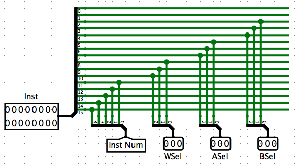
Create a new subcircuit, Decoder. It has exactly one input, the 16-bit instruction Inst. Its outputs are the four control signals from Part 1, plus these four:
-
ALUOp(5 bits) - ALU operation, which is also top 5 bits of Inst.
-
ASel(3 bits) - Selects a register to read from the register file.
-
BSel(3 bits) - Selects a register to read from the register file.
-
WSel(3 bits) - Selects a register to read/write from the register file.
Using the input Inst, generate all eight output signals. To
get you started, here is one part of the decoder:
Next, update your Main circuit. Insert the Instruction Memory (a RAM device), configured with one asynchronous load/store port. Then connect the PC's output to the Instruction Memory's address port. Route the Instruction Memory's output into a 16-bit tunnel Inst. Then rewire the clock, so that the Program Counter, Register File, and Condition Codes are updated on the clock's falling edge.
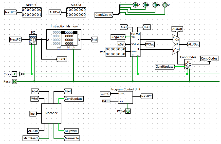
Add your Instruction Decoder to Main. Route Inst into it,
then route its outputs to the rest of your circuit.
Note: Control signals MemRead and MemWrite do not go anywhere in this assignment, but you will need them for the final project.
Test your circuit by right-clicking Instruction Memory, select "Load Image...", then choose an ULNAv2-B image file. Manually poke the clock line. Ensure that all control signals generated by your Instruction Decoder match your ULNAv2-B disassembler.
Sample Output
Here is a sample output from running the instruction decoder. The grader will use different image files when testing your decoder. This sample only shows the disassembly of the last two instructions from bsort.img
$ ./hw4 bsort.img
<snip>
4ec4: instruction class "B"
      this is: addi.
      CondUpdate: 1
      MemRead: 0
      MemWrite: 0
      RegWrite: 1

20e0: instruction class "A"
      this is: br
      CondUpdate: 0
      MemRead: 0
      MemWrite: 0
      RegWrite: 0
Here is a sample output from running a completed multu8.img through the ULNAv2-B emulator:
$ ~/ulnav2-b/ulnav2-b-emu -v multu8.img
PC 0x0000: MOVI r0, 0x41 > c
-- Cycle = 1, PC = 0x0001 --
Register File:
    0: 0x0041    1: 0x0000    2: 0x0000    3: 0x0000
    4: 0x0000    5: 0x0000    6: 0x0000    7: 0x0000
Condition Codes:
  C: f  N: f  V: f  Z: f
Data Memory:
  0x0000:  0000 0000 0000 0000 0000 0000 0000 0000
    ...
  0xfff8:  0000 0000 0000 0000 0000 0000 0000 0000
<snip>
VM halted!
-- Cycle = 103, PC = 0x000b --
Register File:
    0: 0x0861    1: 0x2100    2: 0x00ab    3: 0x00cd
    4: 0x00ef    5: 0x0033    6: 0xe000    7: 0x0009
Condition Codes:
  C: f  N: t  V: f  Z: f
Data Memory:
  0x0000:  0000 0000 0000 0000 0000 0000 0000 0000
    ...
  0x00d8:  0000 0000 0000 0000 0000 0000 0861 0000
  0x00e0:  0000 0000 0000 0000 0000 0000 0000 0000
    ...
  0x01b8:  0000 0000 0000 0000 e000 0000 0000 0000
  0x01c0:  0000 0000 0000 0000 0000 0000 0000 0000
    ...
  0xdff8:  0000 0000 0000 0000 0033 00ef 00cd 00ab
  0xe000:  0000 0000 0000 0000 0000 0000 0000 0000
    ...
  0xfff8:  0000 0000 0000 0000 0000 0000 0000 ffff
Other Hints and Notes
- Ask plenty of questions on the Blackboard discussion board.
- At the top of your submitted files, list any help you received as well as web pages you consulted. Please do not use any URL shorteners, such as goo.gl or TinyURL. Also, do not cite shared data services, such as Pastebin, Dropbox, or Google Drive.
- You are not writing any ARMv8-A assembly for this assignment, but rather ULNAv2-B assembly.
- You have your choice of multiplication algorithm for Part 3. The instructor has successfully implemented both a shift-adder and Booth's algorithm within ULNAv2-B, though admittedly Booth's algorithm is harder to write.
Extra Credit
Sorry, there is no extra credit available for this assignment.