Project 1: Slot Machine
This project is due on Tuesday, March 24, at 11:59:59 PM
(Eastern daylight time). You must use submit to
turn in your homework like so:
submit cs411_jtang proj1 proj1.circ proj1.txt [image1...]
Each submitted file must contain your name and assignment
number. For the Logisim file, place that information in a text label
on the main circuit. For the text file, place that information at
the top of the file. For image files, ensure your name and
assignment number appear somewhere in the image.
In this assignment, you will be building a circuit that implements a slot machine with five reels. The player "wins" if he can stop those so that they display "CS411".
You will slowly build up each component in each part of this
assignment. Be sure to complete each section and test it thoroughly
before tackling the next part.
You will be reusing portions of this assignment for the remainder of this semester. It is in your best interest to design your circuits for maximum readability.
To begin, install the Logisim application. The program is written in Java and should run fine on Windows, macOS, or Linux; the instructor has tested this assignment on macOS. After installing it, you should work through the tutorial to get a feel for the interface. This assignment uses subcircuits extensively, so you should become familiar with that feature.
Part 1: Ripple Adder
The first component to build is a 1-bit (3, 2) adder. The adder has
three inputs, A, B,
and CarryIn. Its two outputs
are Sum and CarryOut. There are
several ways to calculate CarryOut; the following
diagram is one of them:
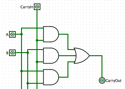
Implement this part of the adder in Logisim. Then add the logic to
calculate Sum.
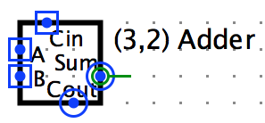
Next, modify this subcircuit's appearance. As a suggestion, draw the
1-Bit Adder's appearance to roughly match the textbook's
symbol:
Then create a 2-bit Ripple Adder subcircuit, that contains two instances of this 1-bit adder. This subcircuit has three inputs: A (2 bits), B (also 2 bits), and CarryIn (1 bit). Calculate the sum of A and B, and then collect the sums into a single 2-bit output Sum. Also add the output CarryOut (1 bit). You will need two splitters for this subcircuit.
Test your 2-bit Ripple Adder via the Poke tool, for a variety of inputs for A, B, and CarryIn.
In your proj1.txt file, calculate your gate propagation delays from when A, B, and CarryIn are set to when the final 2-bit Sum and the 1-bit CarryOut are calculated. When calculating your delays, treat each gate, regardless of type, as 1 delay unit. For example, a AND gate has 1 delay unit. If that same AND gate's top input is inverted, the top path has 2 delay units, while the bottom path's delay is still only 1 delay unit. Therefore, the AND gate's output has a propagation delay of 2 units.
Part 2: 2-Bit Counter
The next step is to create an incrementing counter. Although Logisim's built-in library includes a counter, you are required to construct your own for this project.
In a new subcircuit, connect the Sum of a 2-bit Adder to a 2-bit register. Then feed back the register's value to the adder's A input. Set B to the constant 1 and CarryIn to 0; leave CarryOut unconnected.
The 2-bit Counter subcircuit has three inputs: Increment, Reset, and Clock. Add a 2-bit Value output. The counter should increment whenever Increment is high and upon the clock's leading edge. Any time Reset is high, the counter resets to 0 regardless of Increment or Clock.
Special Restriction: You may not use Logisim's built-in adder, subtractor, or counter for this assignment. Doing so will result in a zero for that portion of the assignment.
Part 3: Karnaugh Map for Game Logic
Now that you have created a 2-Bit Counter, the next task is to design the game logic. The output Value from the counter will be used to light a 7-Segment Display. When Value is 0, show a C; for a 1 show a S; for a 2 show 4, and for a 3 show 1.
Construct seven Karnaugh maps, where each map corresponds to a different segment of the display. For each map, the input is 0, 1, 2, or 3. If the output is 1, show that segment. Draw these Karnaugh maps as ASCII art, saved to proj1.txt. If you instead prefer, draw them on physical paper, take a snapshot, and upload the resulting image with the rest of your files. For each map, be sure to label the axes and calculate the sum of products. Also indicate which map corresponds to which segment.
Part 4: Implement Game Logic
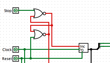
Next a subcircuit Reel. This circuit has 3
inputs: Stop, Clock,
and Reset. Construct a S-R latch, with that latch's
R input connected to Reset
and S connected to Stop. The Not-Q
output feeds into your 2-Bit Counter's Increment; connect Clock and
Reset lines appropriately.
Use your Karnaugh maps to decipher the output of your 2-Bit Counter. This should result in 7 output pins. As an additional challenge, and for extra credit, you will need to add more to this Reel subcircuit. See the Extra Credit section for details.
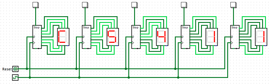
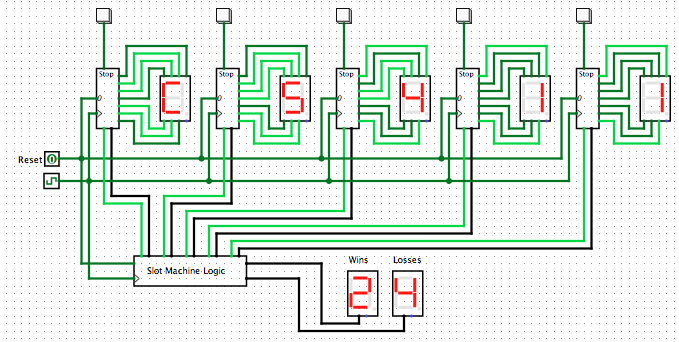
Then design your Main circuit similar to the image at the top of this assignment. Connect a Button to the Reel's Stop. Connect the seven outputs from the Reel to a 7-Segment Display. Repeat this four times. Finally, connect the Clock and Reset lines.
Test this overall circuit by toggling the Clock line manually. Your Reels should rotate between C, S, 4, and 1 in that order. When the user presses a Stop button, that Reel should latch to the displayed value. Use Reset to unlatch all values. Then finally set the tick rate to get the full casino experience. (The instructor can consistently get the value CS411 at 4 hertz or slower.)
Part 5: 16-bit ALU
In this Main circuit, you needed a 2-bit ALU. The final project involves a 16-bit processor, so you will begin constructing your final project starting here.
Create a new subcircuit, 4-Bit Ripple Adder, using two 2-Bit Ripple Adders. The inputs and outputs are similar as 2-Bit Adder, except the buses are now 4 bits wide.
Next construct a new subcircuit, 16-bit ALU. There are three inputs:
- A (16 bits)
- B (16 bits)
- Operation (5 bits)
- Result (16 bits)
- Condition Codes (4 bits)
- Addition (A + B): 1, 3, 7, 9, 11, 12, 13, 15, 23
- Subtraction (A - B): 5, 21
- Logical AND (A ∧ B): 2, 18
- Logical OR (A ∨ B): 0, 16
Then add these 4 condition codes to your ALU:
- Z: Zero
- True when the result from the ALU is exactly zero.
- C: Carry
- True when the carry-out bit of the ALU's last adder unit is true.
- N: Negative
- True if the ALU result is negative (i.e., MSB is 1).
- V: Overflow
- True if the ALU result's MSB does not match the operands.
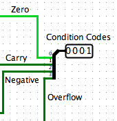
Calculate all four condition codes, regardless of the input operation number. Join the codes into a single 4-bit output pin. Label each bit position for ease of grading.
Other Hints and Notes
- Ask plenty of questions on the Blackboard discussion board.
- At the top of your proj1.txt file, list any help you received as well as web pages you consulted. Please do not use any URL shorteners, such as goo.gl or TinyURL. Also, do not cite shared data services, such as Pastebin, Dropbox, or Google Drive.
- Your proj1.txt should include: calculations of your 2-Bit Adder's propagation gate delay, and the seven Karnaugh maps.
- Be sure to submit both proj1.circ and proj1.txt to receive full credit.
- The logic for the ALU Operations from Part 5 appears difficult, but is actually simple. Write out their binary values, and you should notice patterns in the operations.
Extra Credit
You may earn an additional 10% credit for this assignment by adding
another feature to your slot machine. You are to record and display
the number of times the player wins or loses. A win is defined as
when the user stops all five reels so that they show
"CS411". A loss occurs when the player gets any other
result.
First, add another subcircuit, EC 4-bit Counter. This counter is similar to the 2-bit Counter from Part 2, but instead it counts up, from zero to 15.
The create a new subcircuit, EC Slot Machine Logic. This subcircuit has two instances of EC 4-bit Counter, corresponding to number of wins and number of losses. This subcircuit is to implement the following behaviors:
- As long as any of the five Reels has not stopped, then do nothing.
- When all five Reels have stopped, evaluate each of their internal values. If the Reels' combined value is "CS411" then increment the Win counter, otherwise increment the Lose counter.
- After incrementing one of the counters, the circuit is to do nothing else until the game is reset.
Finally, duplicate your main circuit, calling this new one EC Main. In EC main, add EC Slot Machine Logic and two Hex Digit Displays. Connect all subcircuits and test. Note that you will need to add two output pins from Reel: a 1-bit output that indicates if Stop was triggered, and 2-bit output for that reel's counter value.
Major Hint: You will need to use Logisim's built-in S-R flip-flop subcircuit, instead of two criss-crossed NOR gates as illustrated in Part 4, when building EC Slot Machine Logic and when updating Reel. This is because after the simulation reset, criss-crossed gates are in indeterminstic states, but Logisim's built-in S-R flip-flop defaults to zero.
If you choose to perform this extra credit, put a comment at the top of your proj1.circ Main circuit, alerting the grader.