We built a class to store the geometrical data of the plant and
to render
the geometrical data by perspective projection. This method ensures that the
three dimensional pixel is moved closer to the vanishing point as its distance
to the viewer
increases(Figure ![]() ).
).
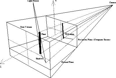
Figure 3: Perspective projection in Model class
We used Z-buffering to decide which pixel of the overlapped objects is visible
to the camera. In addition to the image pixel array, an additional array of
z values is created for the image. This array can be used to remember the
actual depth of each pixel plotted. If the previous pixel was farther
away according to its z-buffer value, then we plot the new pixel and preserve
its depth in the z-buffer array.
Normally, not all the surfaces in the three-dimensional object are parallel to each other,
which means they will face the camera at different angles. Therefore,
we change the
intensity of each surface according to this angle. To find the correct angle
between the light and the surface, we also have to calculate the normal vector
of every surface. If ![]() is the normal vector of a surface and
is the normal vector of a surface and ![]() is the vector describing the direction of the light source, then the intensity
of the light is given as the cosine of the angle
is the vector describing the direction of the light source, then the intensity
of the light is given as the cosine of the angle ![]() between
these two vectors:
between
these two vectors:
![]() (refer to Figure
(refer to Figure ![]() )
)
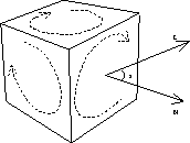
Figure 4: Shading in Model class
To cast a shadow from the light source to the ground, we imagine a set of
lines for all vertices in the object,
each line passing through one vertex and the light source.
Where this line hits
the ground plane, a shadow vertex is formed so we can then draw the projected
shadow polygons using a color darker than the ground plane.