Contents
- Milling a double sided copper-clad board using the S63 Protomat
- Information regarding consumables (size and thickness)
- Material Settings and ProConduct paste Usage
- LPKF starter package drill bits (Part# 129103-1)
- RF starter package drill bits (Part# 116394-1)
- Maintenance
Milling a double sided copper-clad board using the S63 Protomat
The tutorial aims to cover the steps involved in milling a two layer copper-clad board with through hole components.
This tutorial will also introduce the LPKF ProConduct process for plating through-holes and vias.
List Of Symbols
A summary of symbols you will see in this tutorial
 - Indicates a note or information regarding the process described prior.
  - A tip that provides detailed intuition regarding the process described prior.
  - Needs special attention or care. Most often, requires the assistance of a maintenance personnel.
Equipment Checklist
Do Not Use without proper training !
Exercise extreme caution when using equipment and consumables presented in this tutorial.
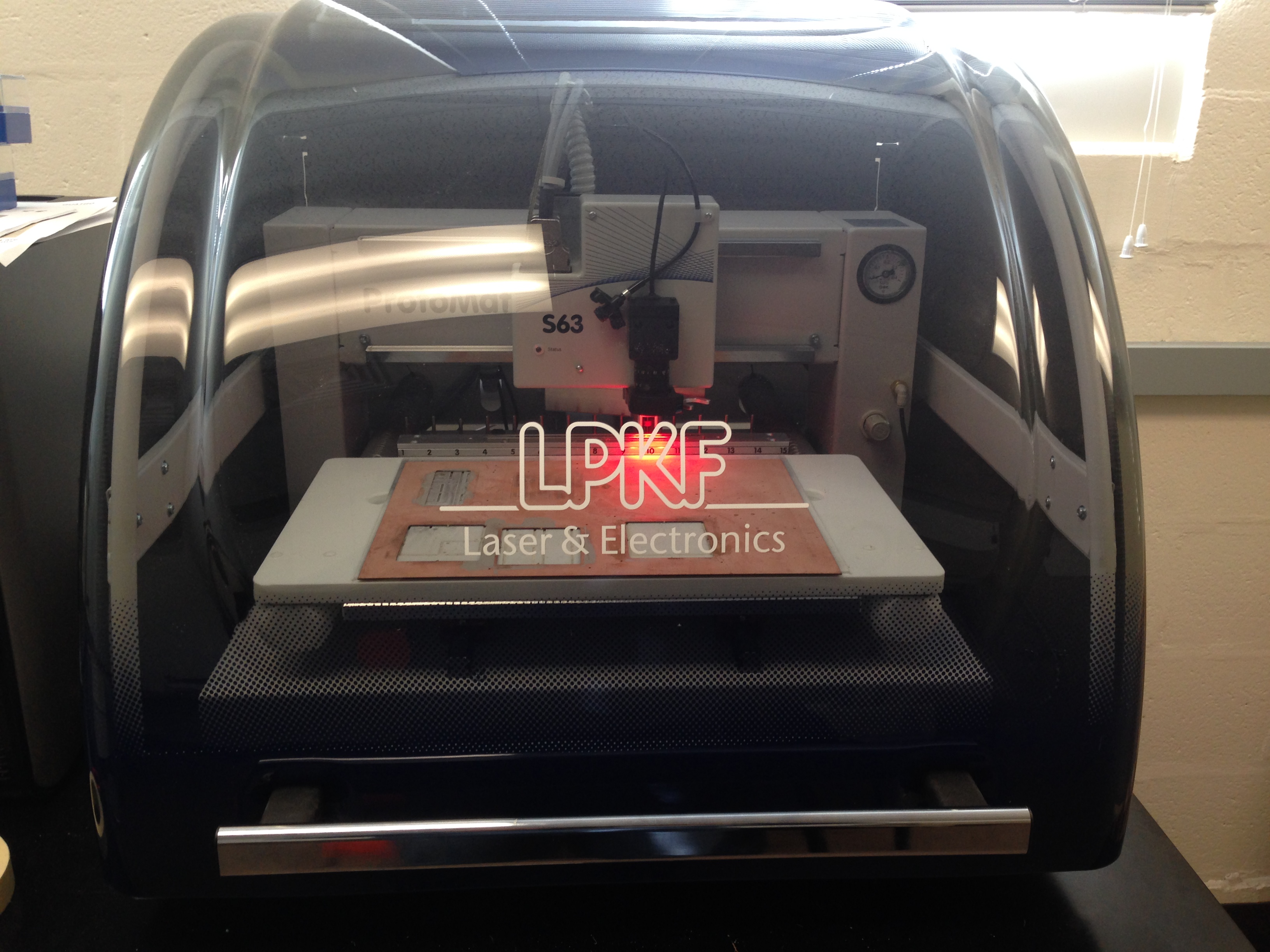
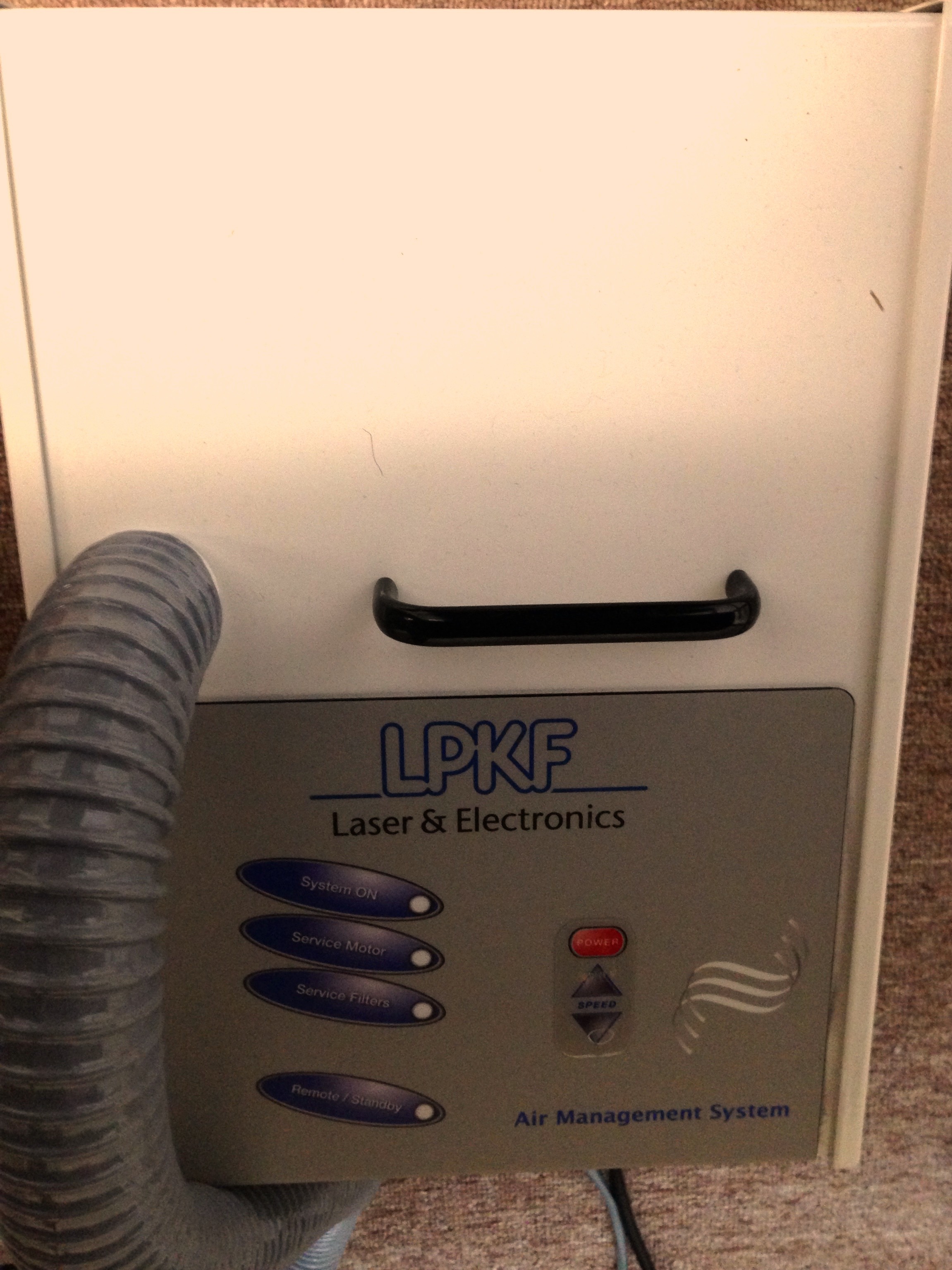
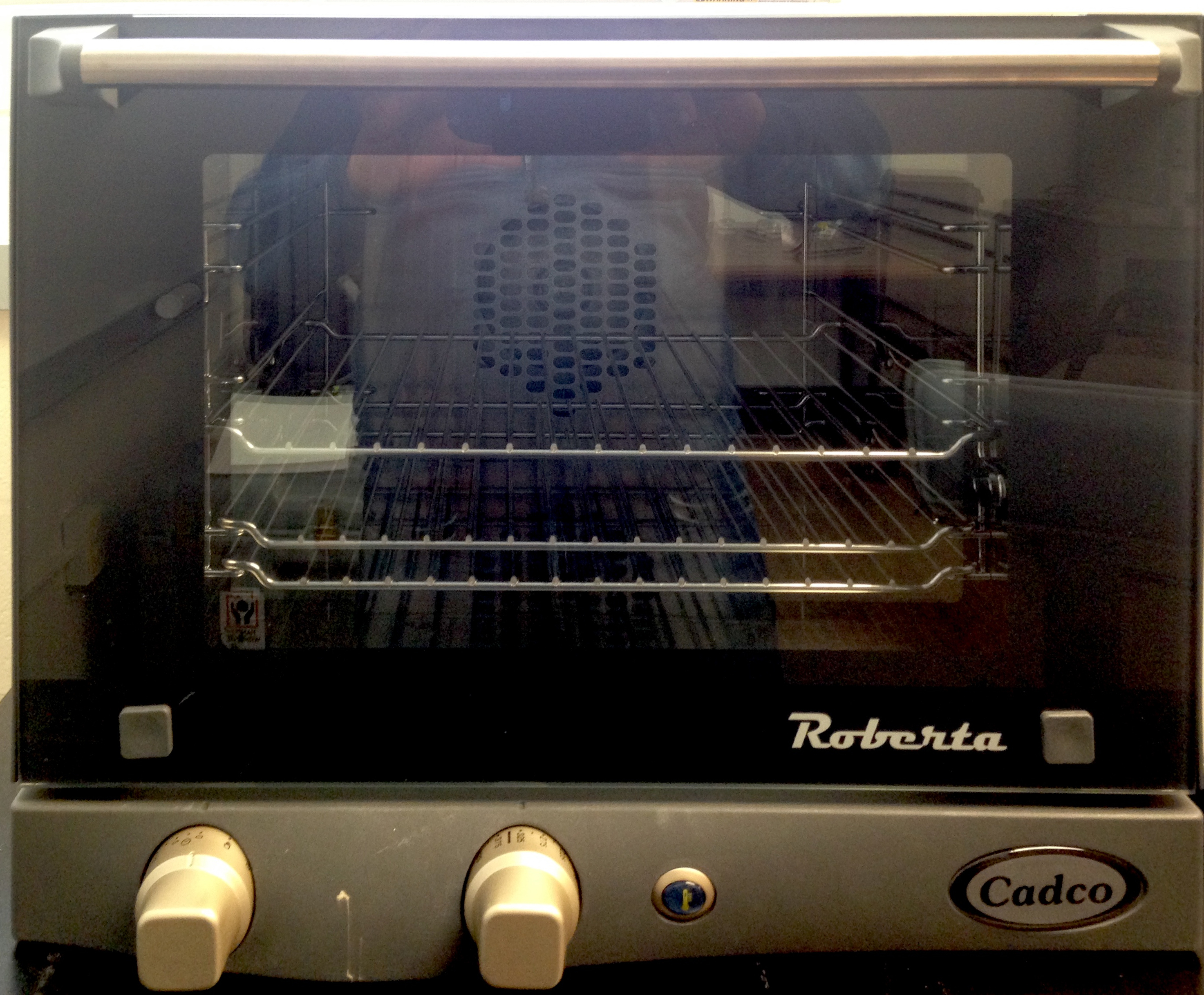
Equipments used in this tutorial
|
|
|
S63 Protomat Milling Machine |
Air Management System |
Oven |
Inventory for milling a copper-clad board
# |
Description |
Illustration |
# |
Description |
Illustration |
1 |
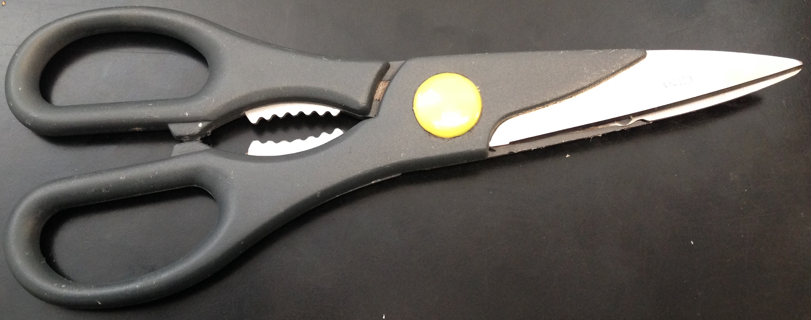
Scissors |
|
7 |
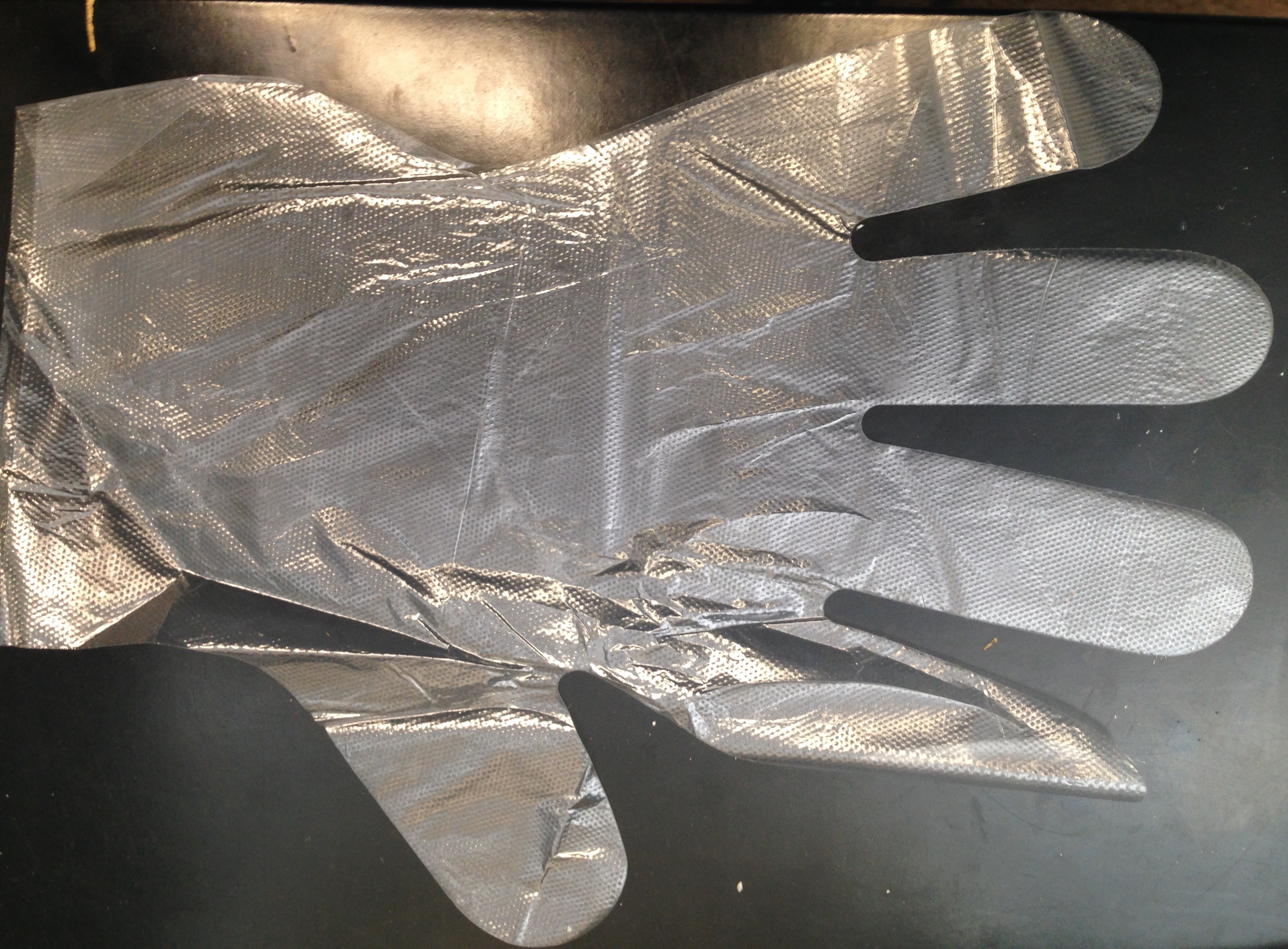
Disposable gloves |
|
2 |
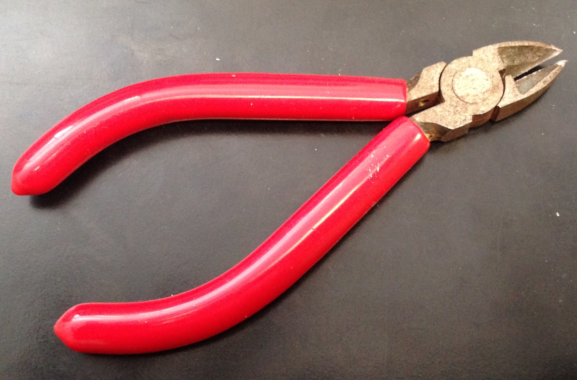
Cutting Plier |
|
8 |
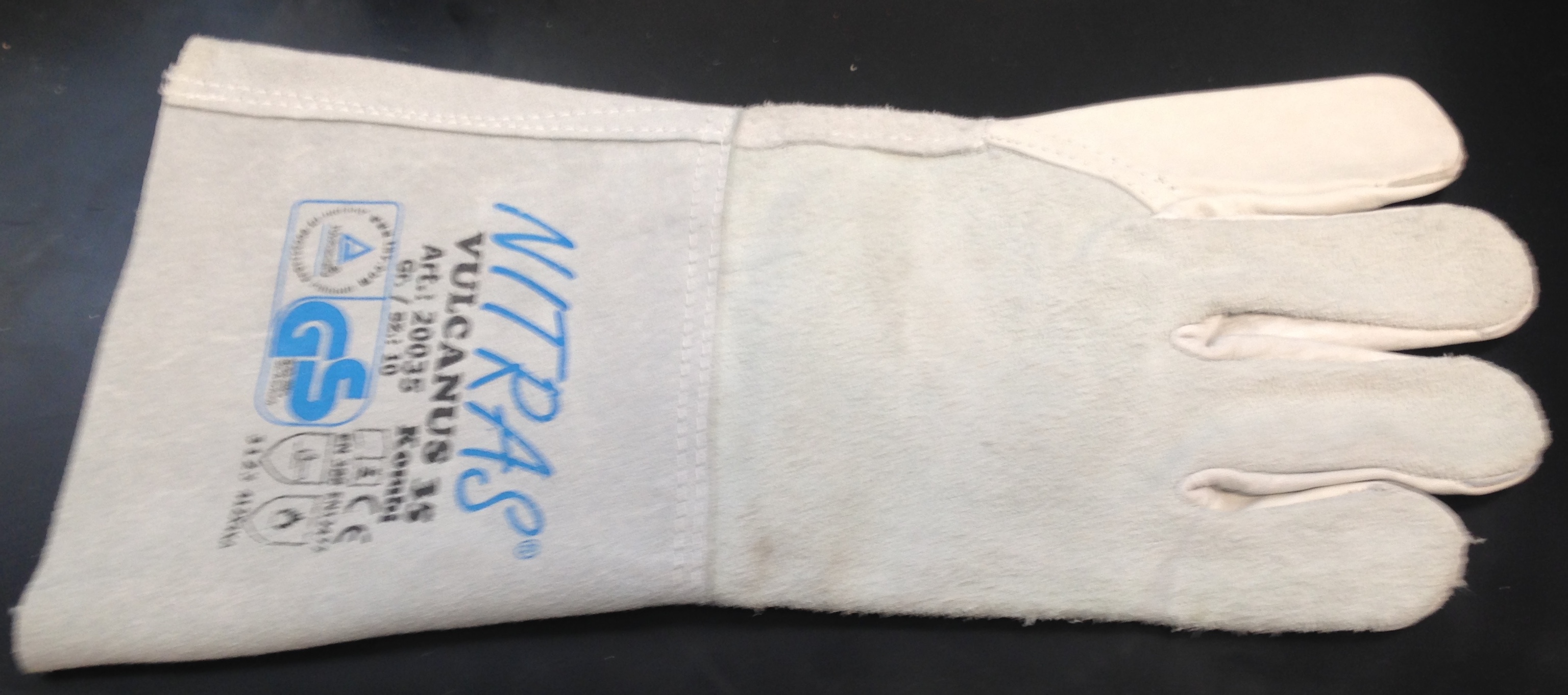
Heavy-Duty gloves |
|
3 |
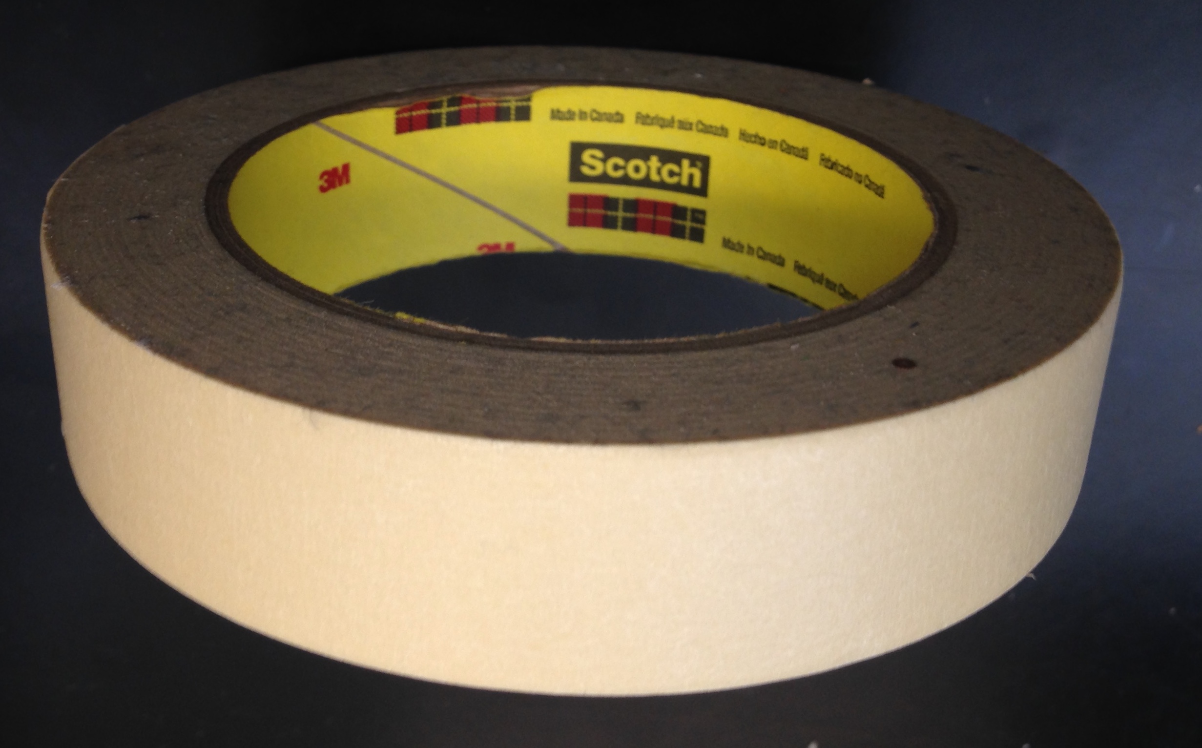
Paper tape |
|
9 |
Squeegee |
|
6 |
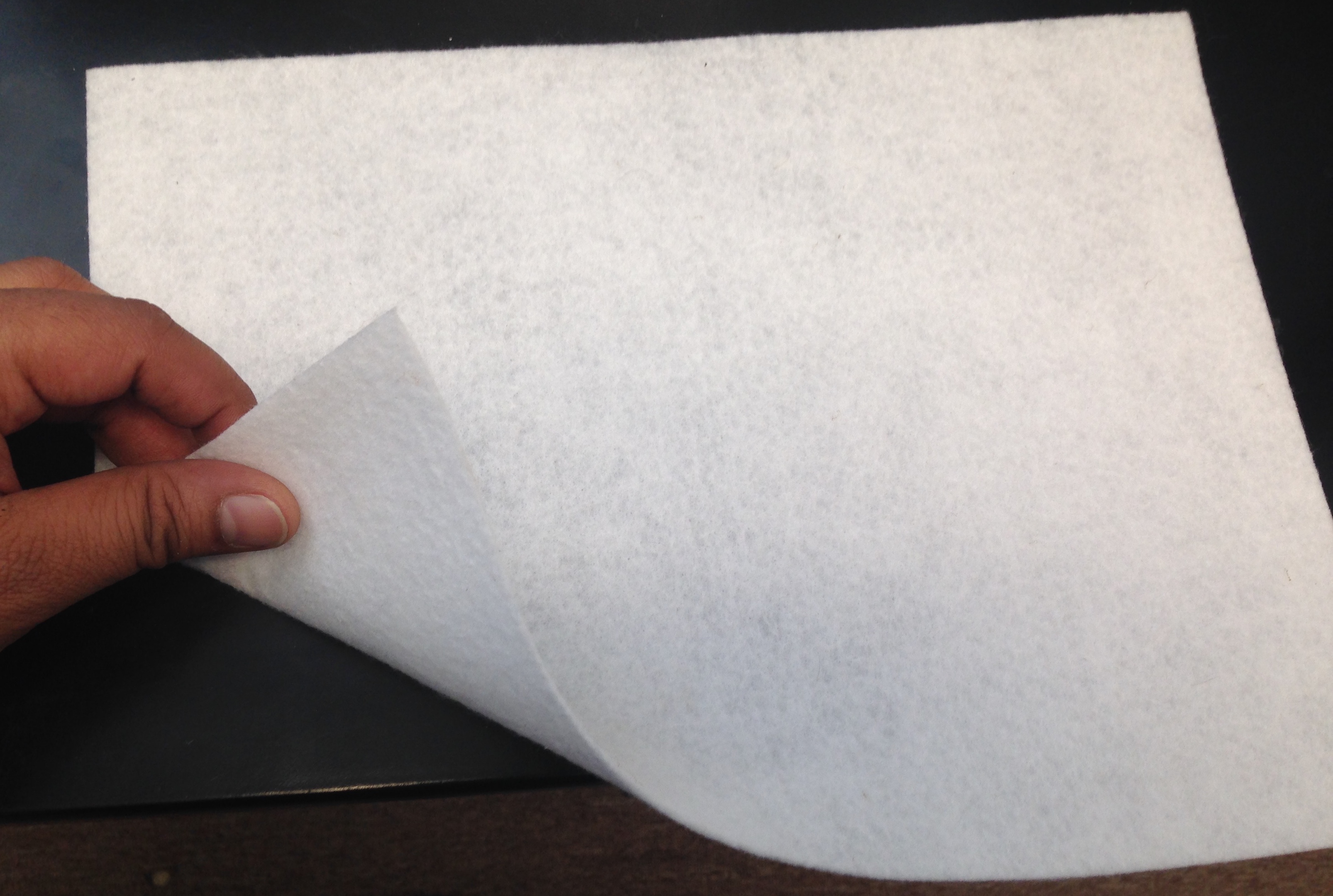
Backing sheet (Absorbent fleece) |
|
10 |
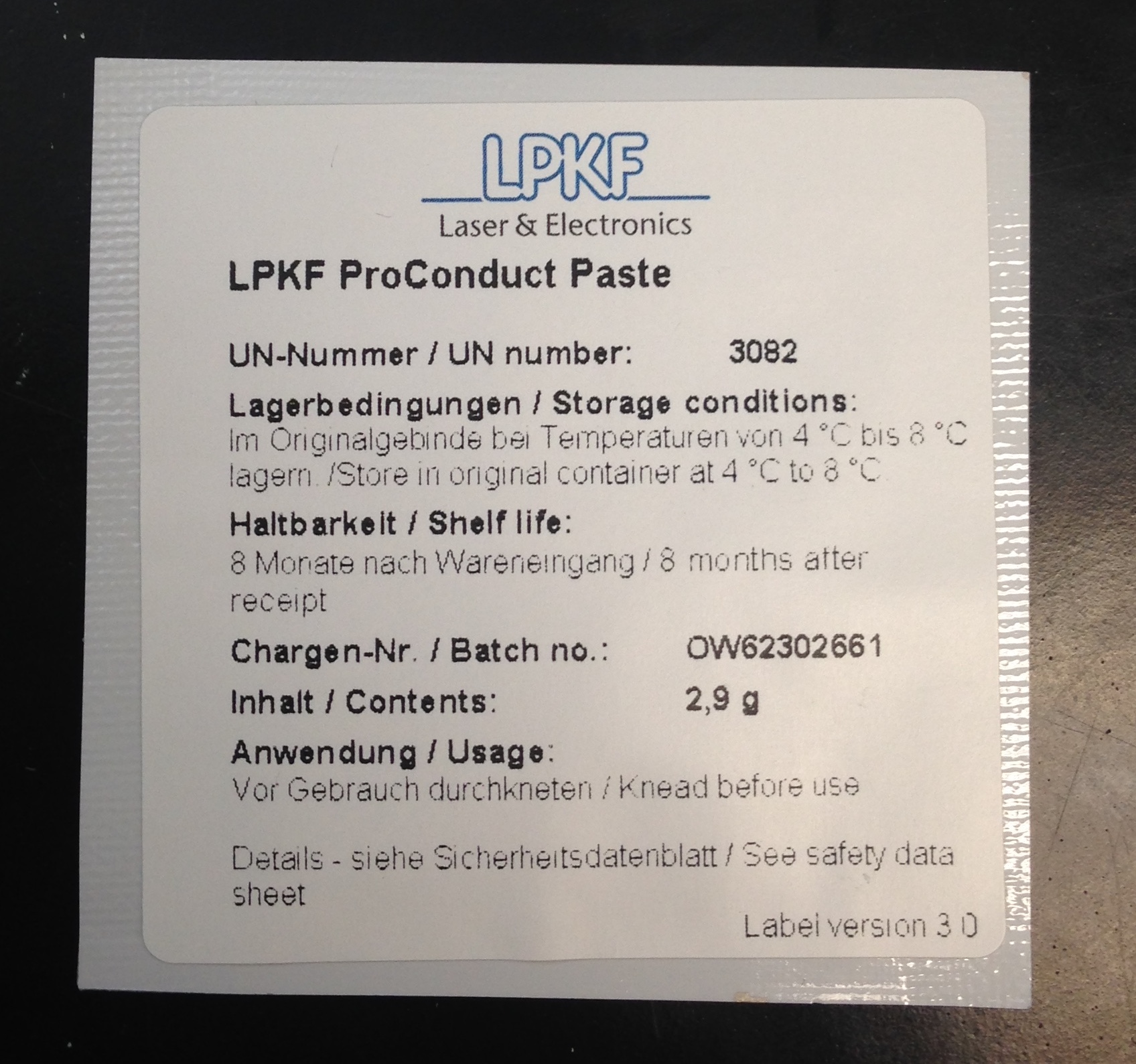
ProConduct Paste |
|
5 |
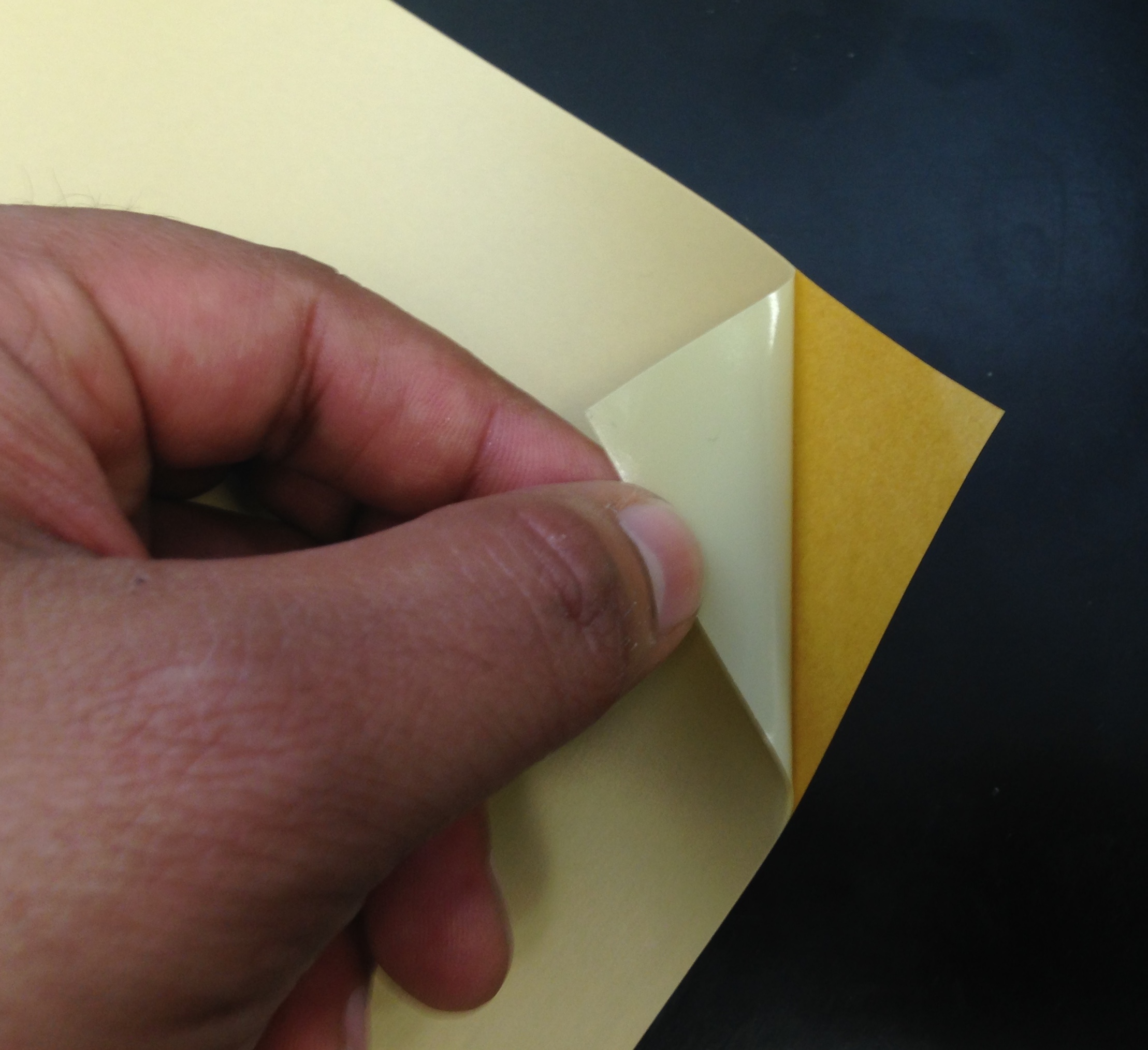
Protection film |
|
11 |
Roller |
|
4 |
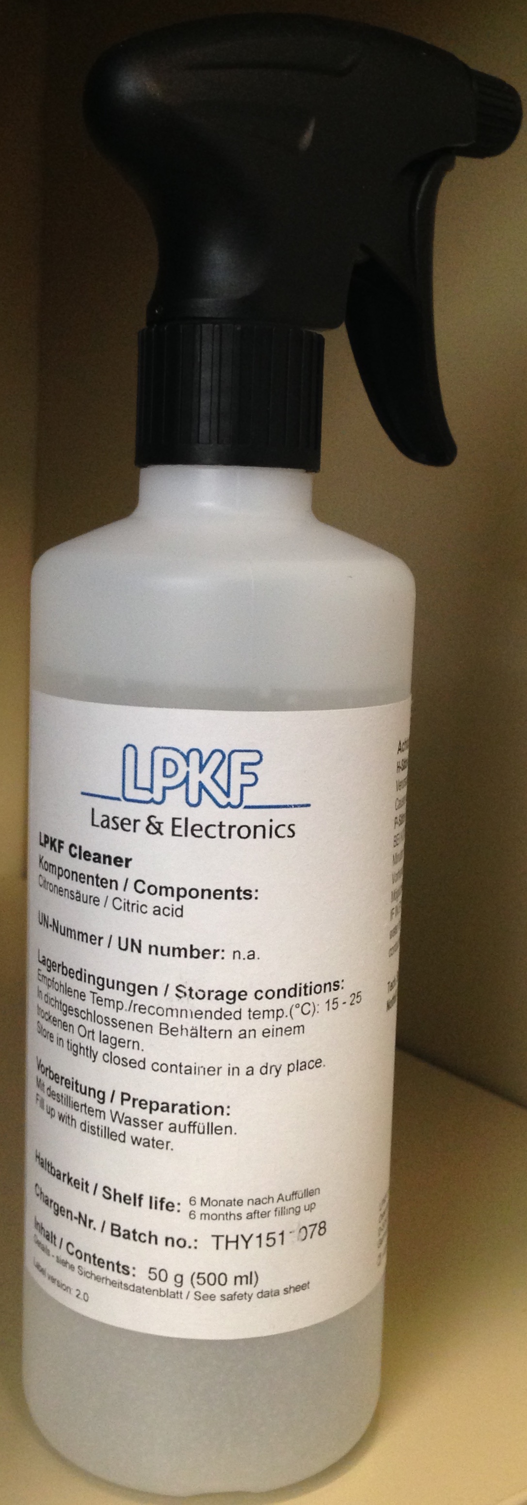
Board cleaning solution |
|
12 |
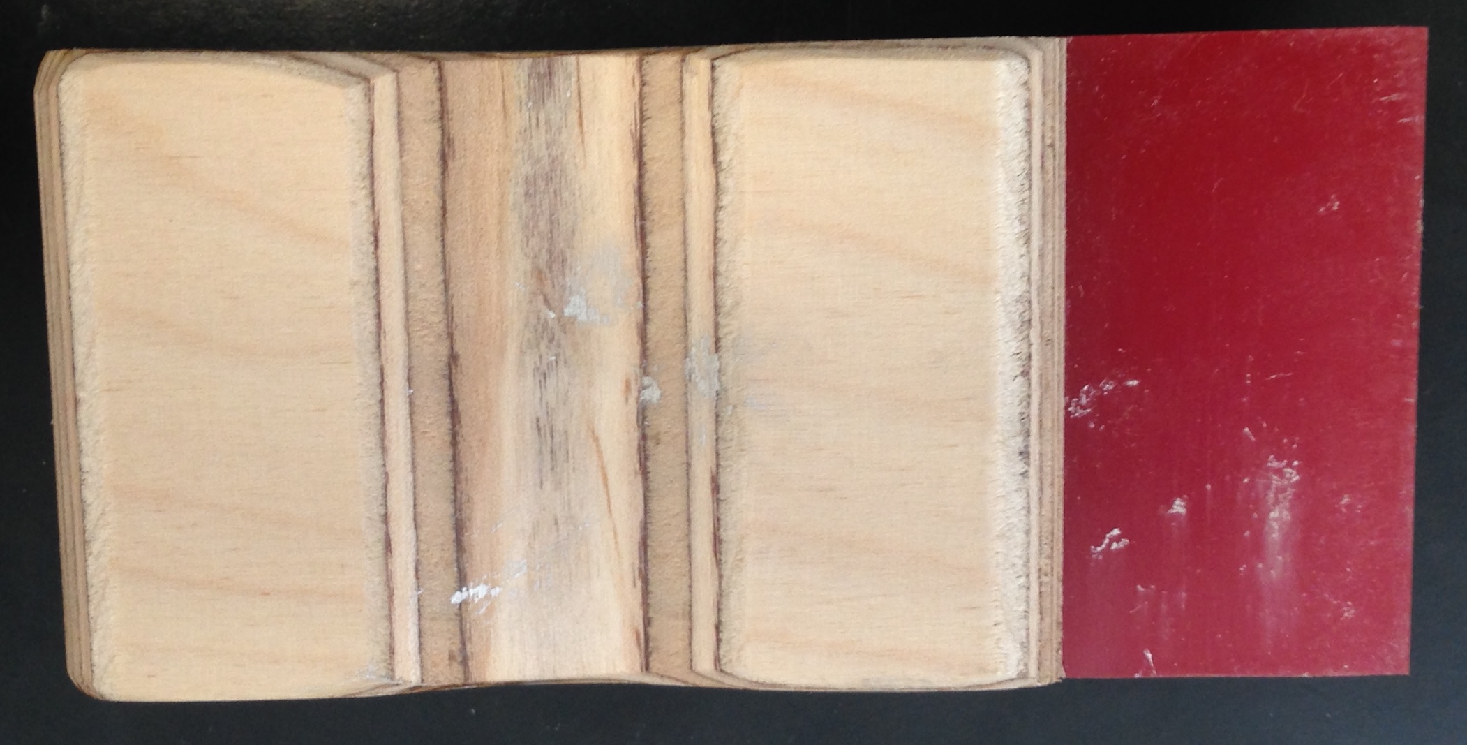
Underlay Material |
|
Board Setup
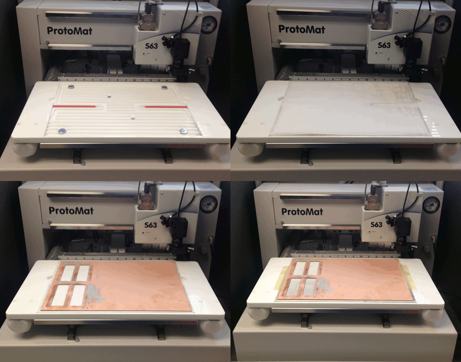
Open the S63 Protomat enclosure and place the 'Underlay Material' on the vacuum table attached to the S63 Protomat. If the 'Underlay Material' appears to be curved, flatten it out by affixing small amounts of paper tape along it's borders to the vacuum table edges. |
|
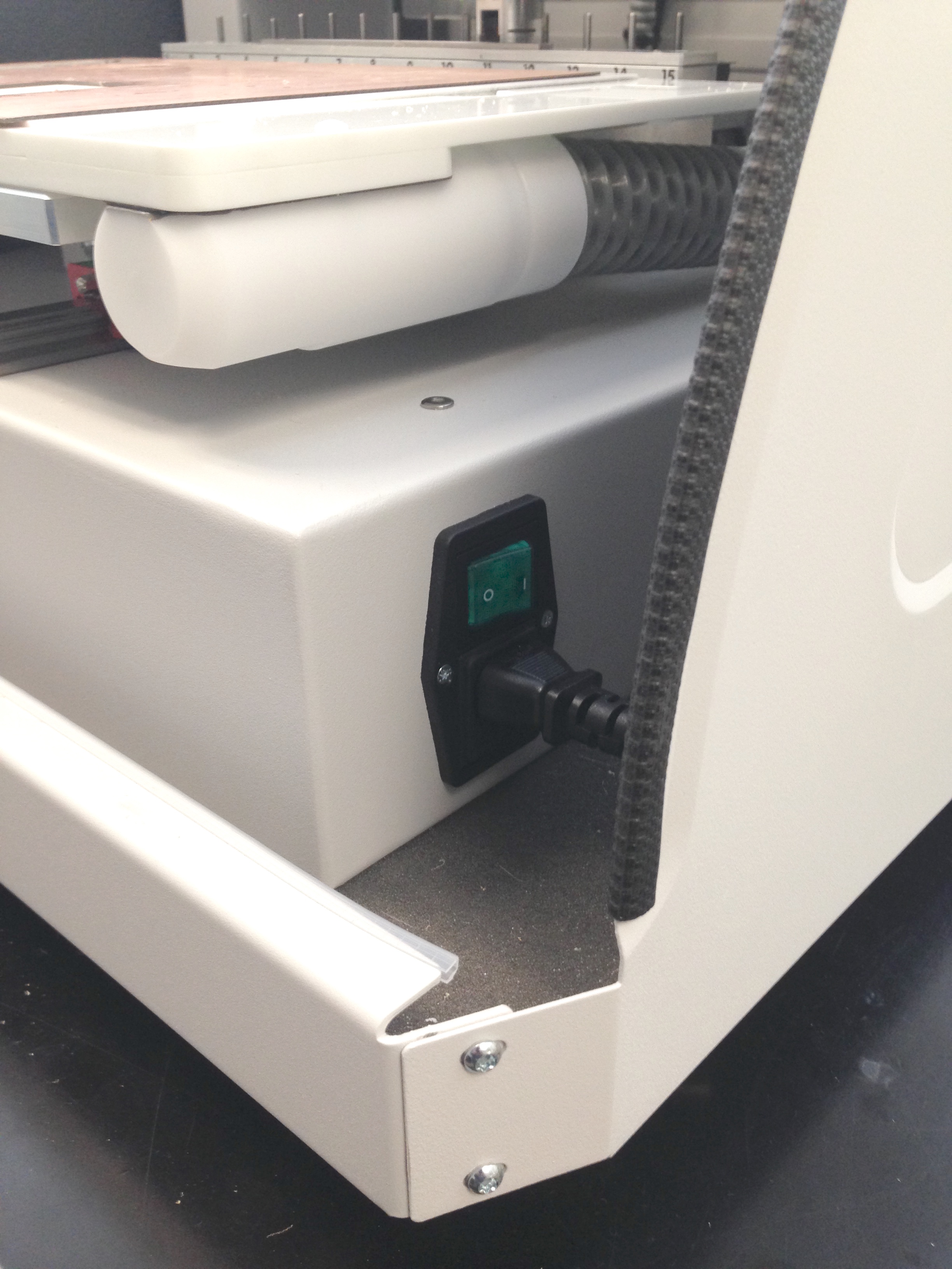
Switch on the S63 Protomat and pull down the enclosure lid. |
|
Circuit Pro Setup
To mill the board, we will use LPKF's Circuit Pro. The following files must be prepared prior to the milling process.
- Gerber file for "Top" layer
- Gerber file for "Bottom" layer
- Gerber file(s) for inner layer(s) - (For more than two layers only)
- Gerber file for board "Outline"
- Excellon/NC Drill file
Read this tutorial to find tips on preparing appropriate via sizes and proper design traces before attempting to mill your board.
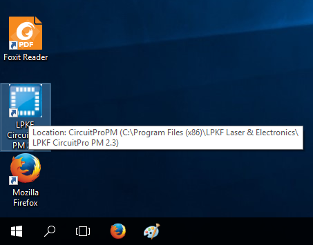
Find LPKF's Circuit Pro application shortcut and launch it. |
|
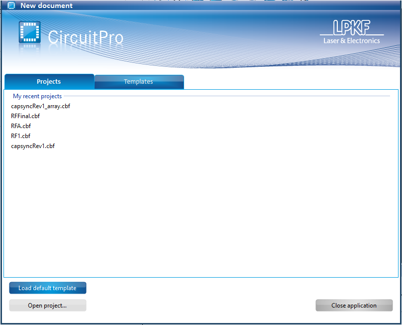
You will be presented with a list of previously opened projects. If you wish to open an existing project (from the 'Projects' tab), choose the project at this point. |
|
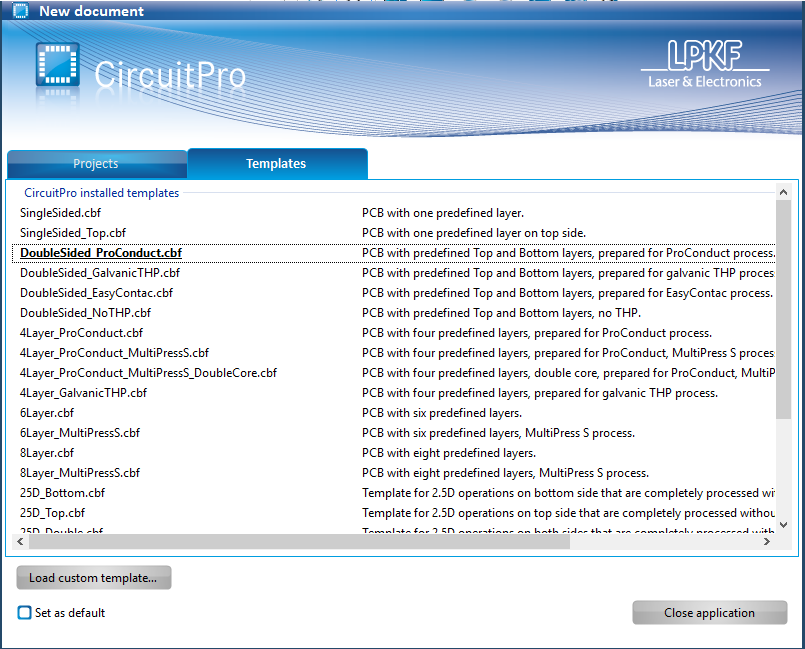
Use the 'Template' tab to choose the configurations template for the current project. Since we are milling a two-layer board, choose the 'DoubleSided with ProConduct' template file. |
|
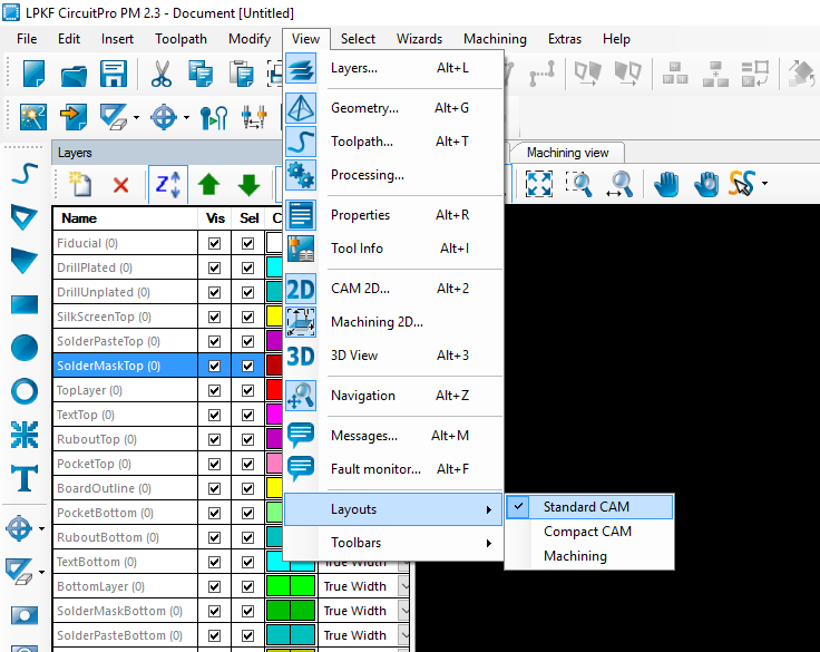
Next select 'View->Layout->Sandard CAM' to setup the standard layout. |
|
Connecting the Milling Machine
If the computer running CircuitPro is not connected to the milling machine, then the connection must be established manually. Ensure that the serial to usb cable behind the milling machine is firmly attached to the USB port of the computer. |
|
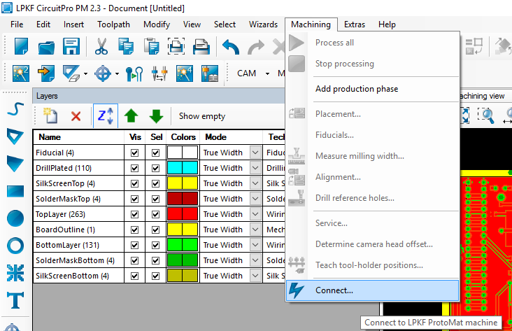
Navigate to 'Machining' option on the main toolbar and select 'Connect'. |
|
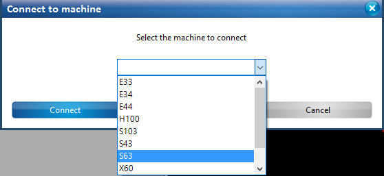
In the pop-up dialog box, select S63 from the drop down list and click 'Connect' |
|
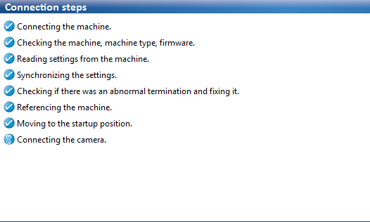
CircuitPro performs a series of checks. If all the checks succeed, a connection with the milling machine has been successfully established. |
|
Process Planning
Initiate the 'Process Planning Wizard' by selecting the respective icon from the wizards toolbar within CircuitPro |
|
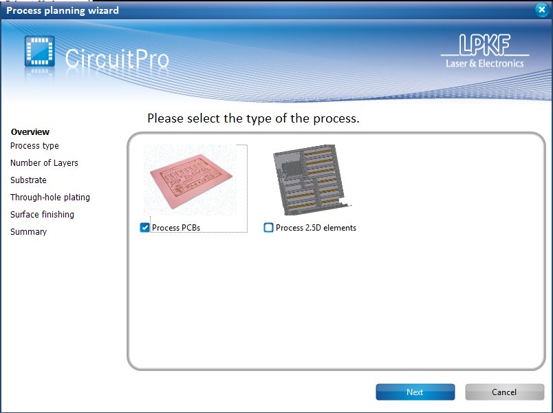
Checkout 'Process PCBs' from available choices and click on 'Next' to proceed. |
|
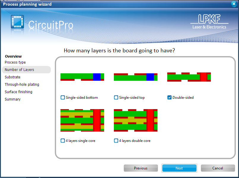
Checkout 'Double-sided' from available choices for the number of layers and click on 'Next' to proceed. |
|
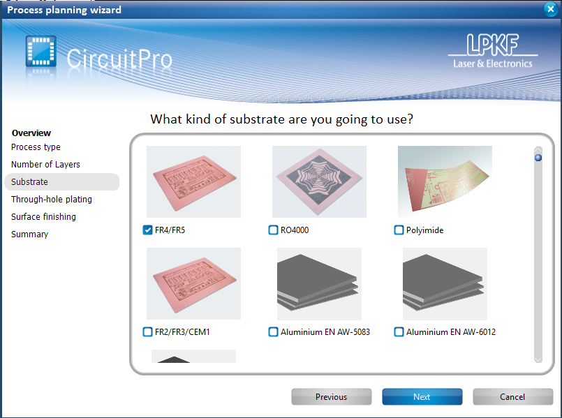
Checkout 'FR4/FR5' from available choices for substrates and click on 'Next' to proceed. |
|
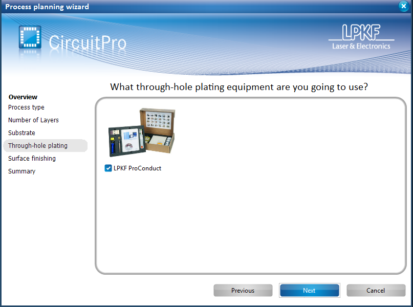
Checkout 'LPKF ProConduct' for the through-hole and via electroplating process and click on 'Next' to proceed. |
|
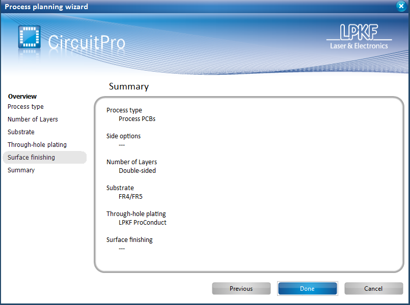
A summary of the selected options will be listed. Click on 'Done' to complete process planning. |
|
Importing Gerber Files
Initiate the 'Import Wizard' by selecting the respective icon from the wizards toolbar within CircuitPro. We will import the gerber and drill files prepared prior to the milling process. |
|
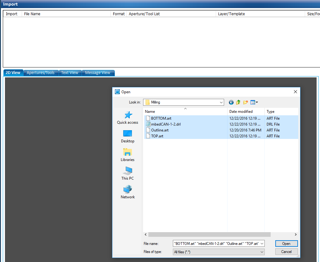
Use the file selection wizard to browse to the location of your gerber files and Control-click and drag to select all the layers and drill files. Click on 'Open' to proceed. |
|
Choose the appropriate label for each imported gerber file from the drop down list. For e.g. the bottom layer gerber file will be assigned the label 'BottomLayer'. |
|
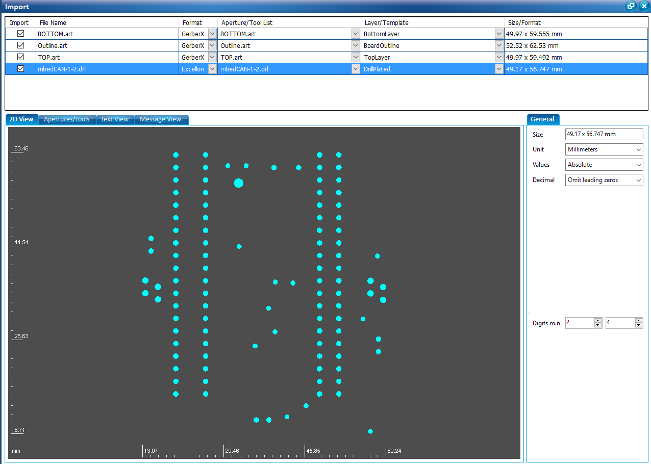
Appropriate labels assigned for each file in a two-layer design. The layout for each file imported is also shown at the bottom when the respective file is highlighted. |
|
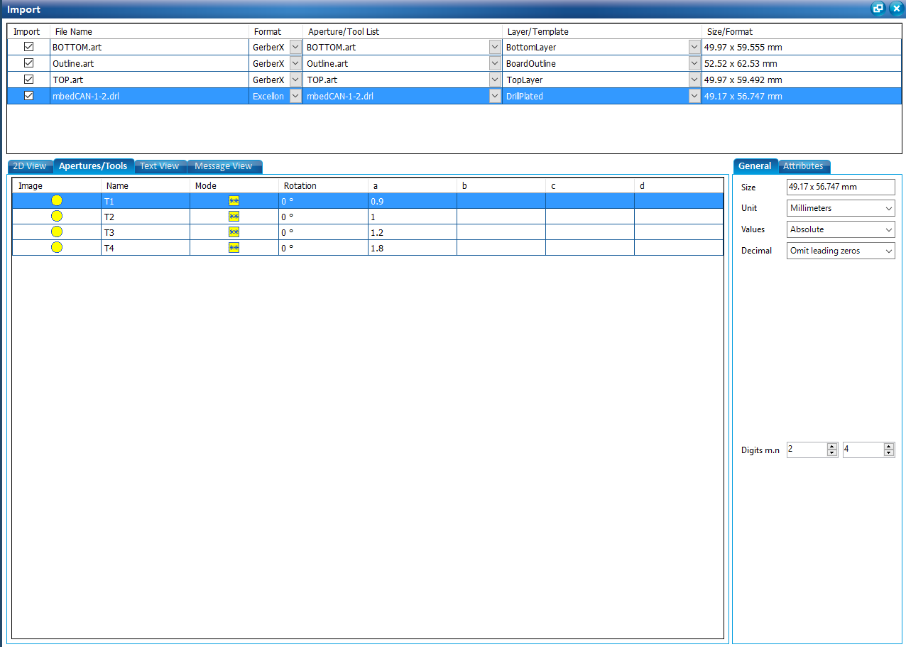
You can verify the drill sizes in your design by selecting the drill file and then selecting the Apertures/Tools tab. The General tab on the right panel allows for custom 'Units' for the drill sizes. |
|
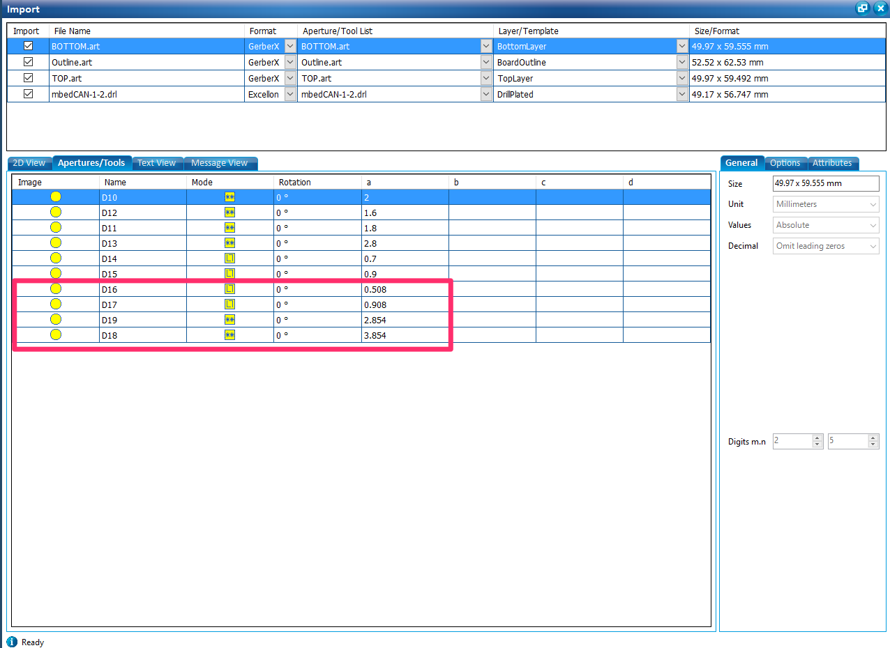
The Apertures/Tools tab when selected while other layers are selected provides a summary of the drill sizes while milling over the design. Best results are achieved when the drill sizes are limited to vary within 0.1 mm. In this example, some of the dimensions do not meet this criteria. This could potentially cause the milling tool to leave unwanted copper traces in areas with specified clearances. Consult the design tool manual to adjust these settings. |
|
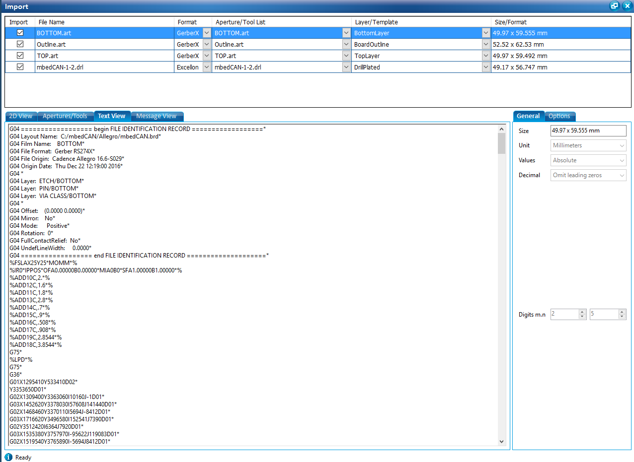
The Text View Tab lists the contents of the highlighted layer's Gerber file. |
|
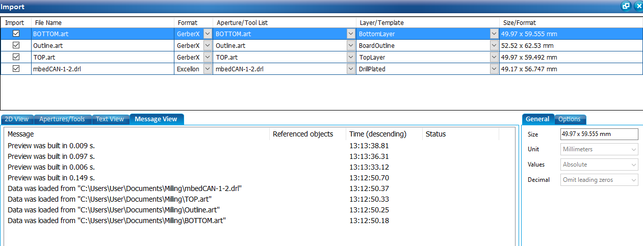
Message View displays preview loaded times and paths to the files imported. |
|
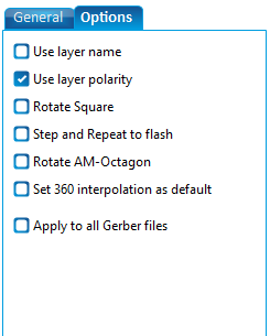
When a layer is highlighted within the top panel, the Options tab (bottom right panel) provides a list of customizable options. |
|
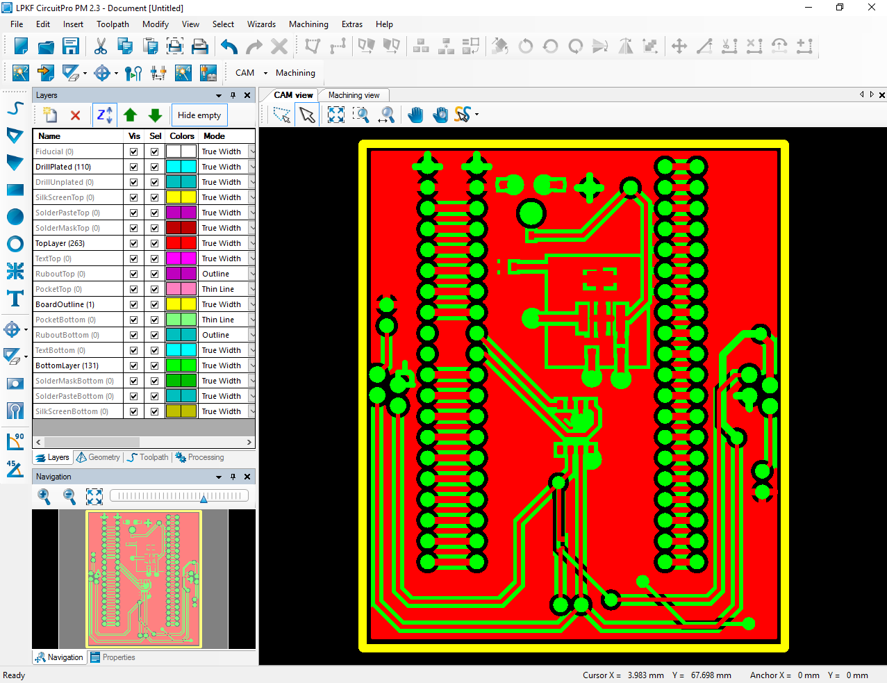
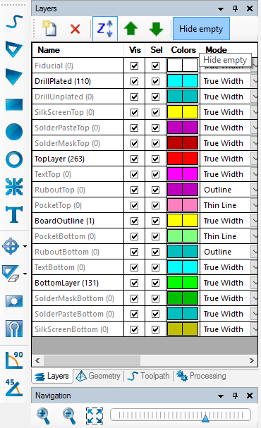
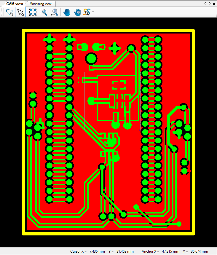
Once the gerber file import process is complete, click on the "OK" button to close the panel and return back to the main window. The layout for the design will be displayed in the "CAM View" panel. On the left, a listing on all the layers imported will be presented. The number of CAM routes will be displayed between the brackets beside each layer. |
|
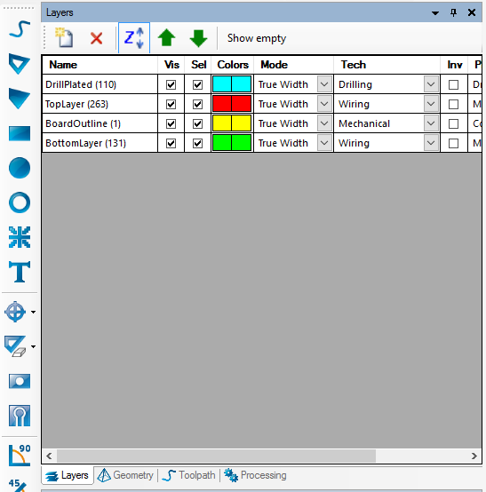
The "Hide Empty Layers" option may be enabled to have a compact listing of only the necessary layers imported in the previous step. |
|
Assigned layer settings for each imported file can be modified using the set of configurable options available for each layer. |
|
Creating Rubout Layers
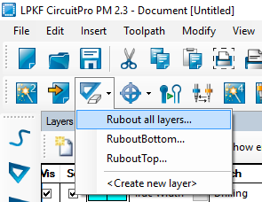
To obtain a finer milling finish (removal of copper traces between circuit lines), "Rubout" layers maybe created for one or more layers in the design. The Rubout layer selection wizard maybe instantiated by clicking on the appropriate icon as shown in figure. |
|
Rubout regions may be created for all layers or for individual layers. Instantiate the Rubout dropdown list by clicking on the dropdown caret beside the Roubout region creation icon. Select the appropriate option, from the dropdown list, to create the Rubout region for your design. |
|
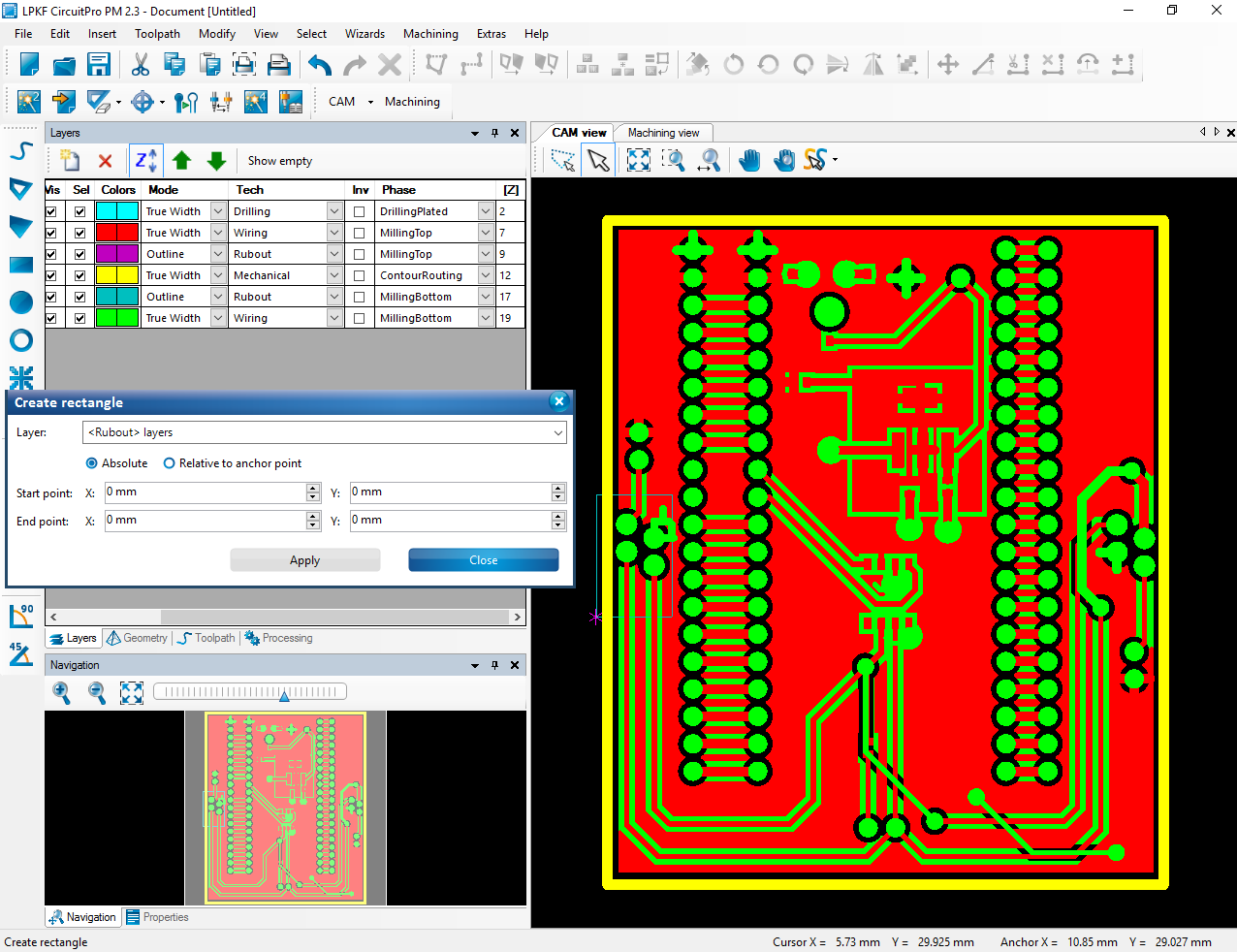
Rubout regions can be specified by "Absolute" dimensions or can be defined relative to an anchor point (Asterisk symbol in 'CAM View'). |
|
It is also possible to use the CAM view to select an anchor point and while holding the left mouse button, click and drag the cursor to define a Rubout region. Once the Rubout region has been defined click on "Close" to quit the Rubout selection panel. New Rubout layers will be created in the list of layers. |
|
Creating Fiducials for Alignment
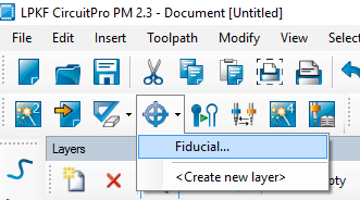
To assist the CAM head in the alignment of different layers of the design, it is necessary to create Fiducial markings in close proximity of the board outline. The create fiducials wizard may be initiated by selecting the appropriate icon, as shown, from the wizards toolbar. |
|
Select 'Fiducial' from the drop down list to enter the fiducial creation model in the 'CAM View'. |
|
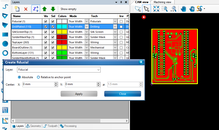
Fiducial may be created at Absolute positions specified by the x and y co-ordinates or they maybe relative to an anchor point. It is also possible to use the left mouse click to create a fiducial marking in the 'Cam View'. |
|
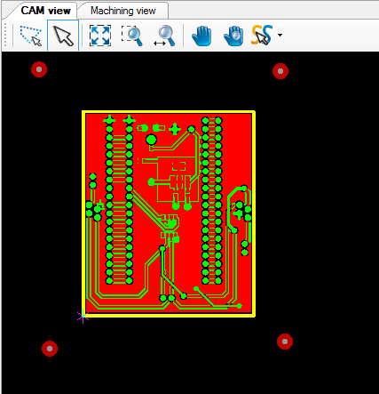
Create one or more fiducial markings in close proximity to the board design outline. Make sure it's far enough so that the protection film does not cover up the fiducials during the drilling phase later in the milling process. Exit the Fiducial creation panel by clicking on close once the required number of fiducials have been created. |
|
Generating CAM Toolpaths
Before we start the milling process, the routing toolpaths for insulation and contour of the imported design must be generated. The 'create insulation and contour routing toolpaths' wizard may be initiated by selecting the appropriate icon, as shown, from the wizards toolbar. |
|
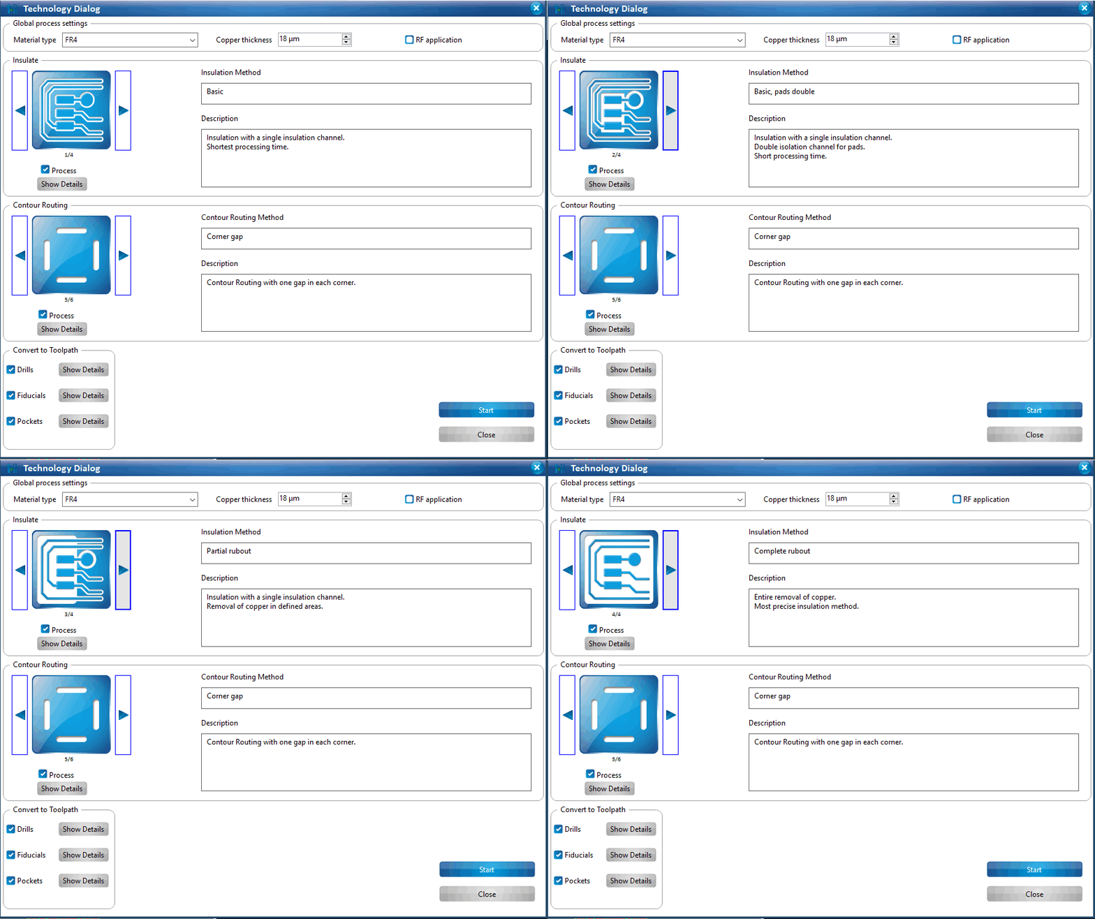
A technology dialog will be instantiated where custom options for milling both insulation and contour is available. Under insulation, one may choose between different methods which varies the amount of milling effort. |
|
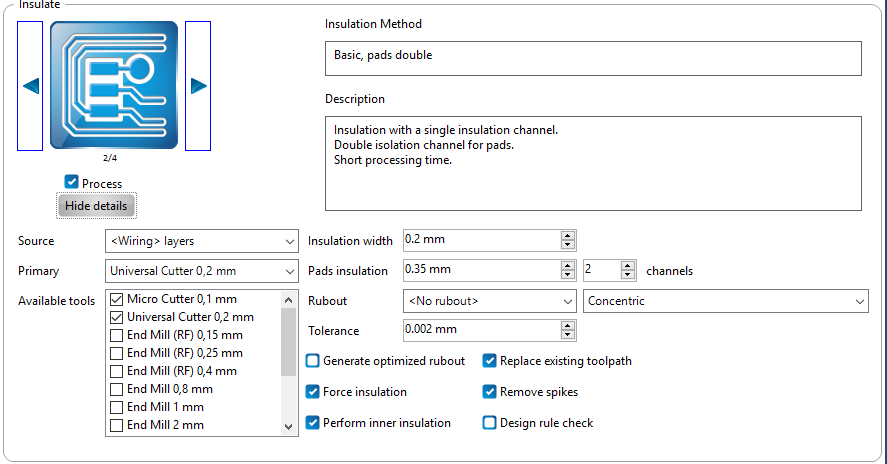
Access the detailed customization options under 'Insulation', using the 'Show Details' button. It is possible to customize the specific drill bits (Primary) used for a specific Source of insulation. Insulation width and pad insulation values can be customized as well. For most designes, you may use the illustration of the settings, on the right side, as a reference. |
|
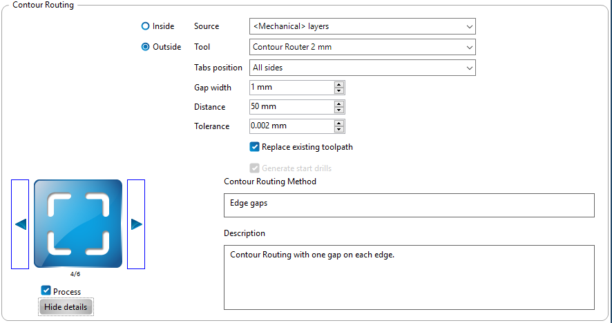
Under 'Contour Routing', one may choose between different methods which varies the slotting scheme used for clipping off the design from the base copper plate. The options available are 'No gaps', which completely separates the design from the base board, the other options are 'Horizontal Gaps', 'Vertical Gaps', 'Edge Gaps', 'Corner gap' and 'Equidistant Gaps'. The 'No Gaps' option would be ideal when the design does not include 'vias' or 'through-holes'. |
|
Access the detailed customization options under 'Contour routing', using the 'Show Details' button. It is possible to mill a contour gaps around either the 'Inside' or 'Outside' edge of the board outline. Depending on the proximity of components in the design, one may choose between either of the options. Unless, otherwise required, the illustration on the side has the recommended settings to be used. |
|
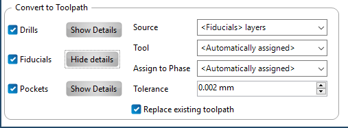
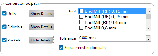
Unless otherwise specified, you may use the illustration on the side as reference, for configuring the settings for 'Drills', 'Fiducials' and 'Pockets' under 'Convert to Toolpaths'. |
|
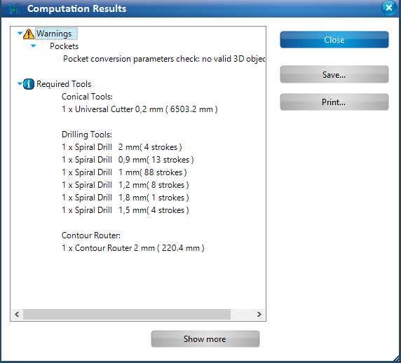
Once the toolpaths have been generated, a summary of the Computation results are displayed. The required tools (drill bits) for the job is summarized. You may safely ignore the 'Pocket conversion check' warning. Click on 'Close' to exit the summary dialog. |
|
The 'Toolpaths' tab at the bottom left panel in the main view, may be selected to review the toolpaths generated during each phase of the board production process. |
|
Tool Magazine Selection
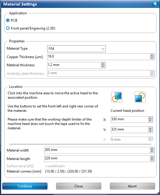
Prior to selecting the drill bits for the tool magazine, It is recommended to configure the 'Material Settings' depending on the type of copper clad board used during board production. Access this dialog box by Navigating to 'Edit' in the main toolbar. Under 'Edit' select 'Material Settings'. Consult the Material Settings Table at the bottom of this tutorial to assign the recommended settings for 'Copper Thickness' and 'Material Thickness'. |
|
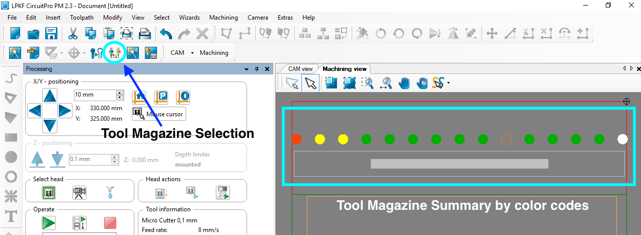
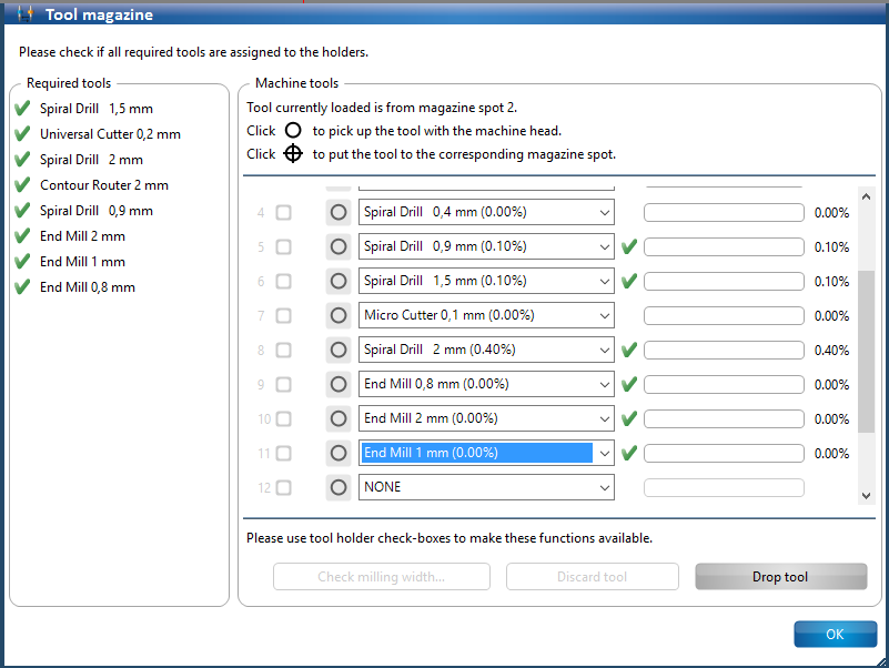
When the milling machine is used for the first time, the tool clamps behind the tool magazine (located behind the vacuum table platform) need to be populated with the required drill bits. In this step we will determine the drill bits missing. The 'Tool Magazine Selection' wizard may be initiated by selecting the appropriate icon, as shown, from the wizards toolbar. |
|
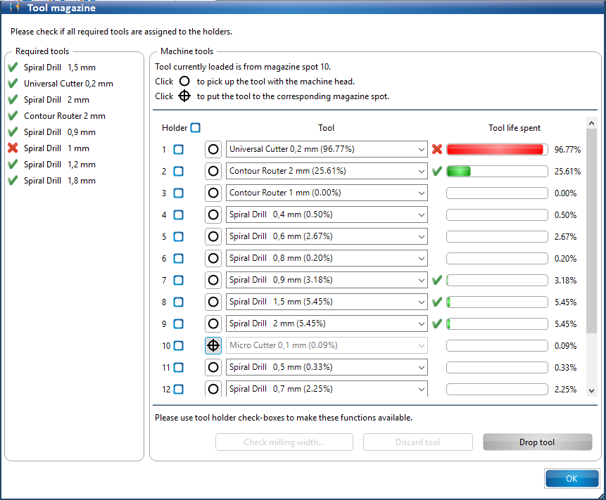
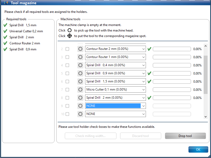
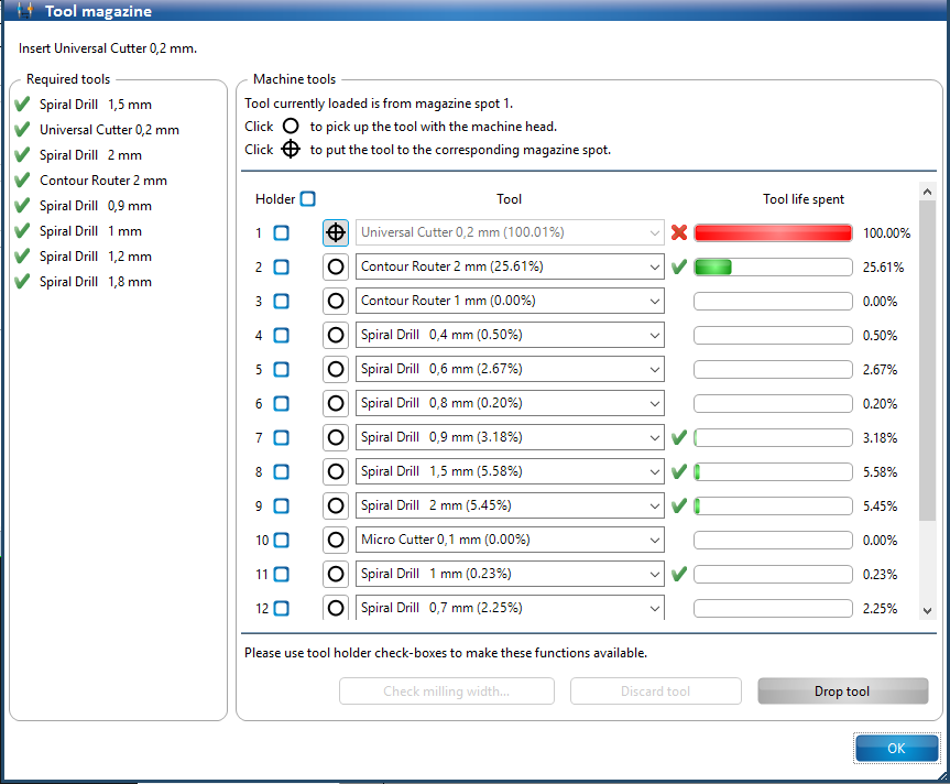
The 'Tool Magazine Selection' dialog has a summary of required tools for the current design. A missing drill bit has a 'cross' next to it. |
|
Prior to milling, the milling head must be trainined for adjusting the tool height (Distance from the copper board to the drill bit tip). |
|
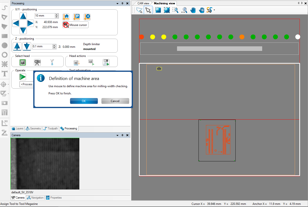
A dialog opens up which prompts to define the milling area to check the milling width of the tool that needs training. |
|
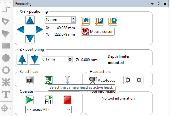
At any stage, for precise determination of a location on the board, utilize the "Processing Panel' to navigate the milling head to the desired location. |
|
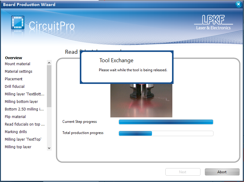
The milling machine confirms the current drill bit on the milling head and performs an adjustment. It performs a tool exchange if required. |
|
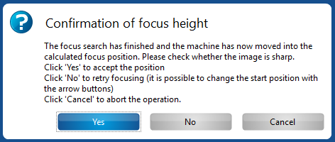
Depending on the drill bit, the milling head mills a line (Universal drill bit or Micro Cutter) or a circle (End Mill), and adjusts the camera head to provide an updated camera view feed. If the focus looks good, click "OK" to confirm. Click "No" for the milling head to retry focussing the camera. |
|
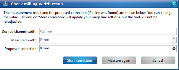
The milling machine communicates the camera feed to the computer, where the image is processed to determine milling width corrections if necessary. If corrections are required, the 'Check milling width results' dialog will provide the proposed correction required. Click on 'Store correction" to store the proposed correction into the milling machine. |
|
Board Production
Ensure that the copper clad board has been affixed firmly to the vacuum table top and the enclosure lid is in the closed position. |
|
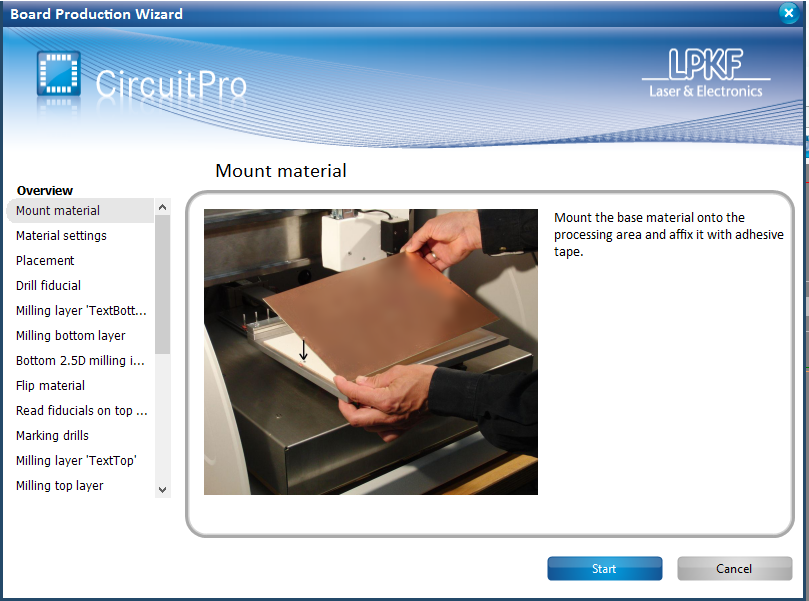
You will be presented with a illustration of mounting the copper clad board onto the vacuum table top. Since this process was covered in the Board Setup step, we will proceed by clicking on 'Start'. |
|
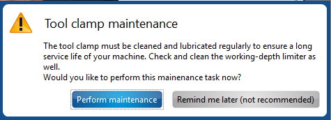
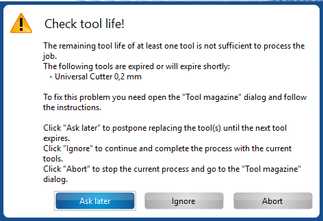
Warning messages indicating 'Tool Clamp Maintenance' and 'Check Tool Life!' need to be reported to maintenance personnel if encountered. |
|
The 'Material Settings' dialog configuration was covered as a part of 'Tool Maganzine Selection' step. It is essential to configure the same during the 'Tool Magazine Selection' step. Click on 'Continue' to accept the configured settings and proceed. |
|
The placement dialog box (Which can be manually access from the 'Machining' option in the main toolbar), allows for relative positioning (based on an anchor point, rotation as well as creating multiple copies of the design along both the design's vertical and horizontal dimensions. You can also use the mouse to grab the design (along the black outline) within the 'Machining View' and move it to a desired milling location on the board. |
|
CircuitPro offers the option to save the current configuration which comprises of the configuration settings, template and the design. If you wish to save a copy of the same, you may do so at this stage. |
|
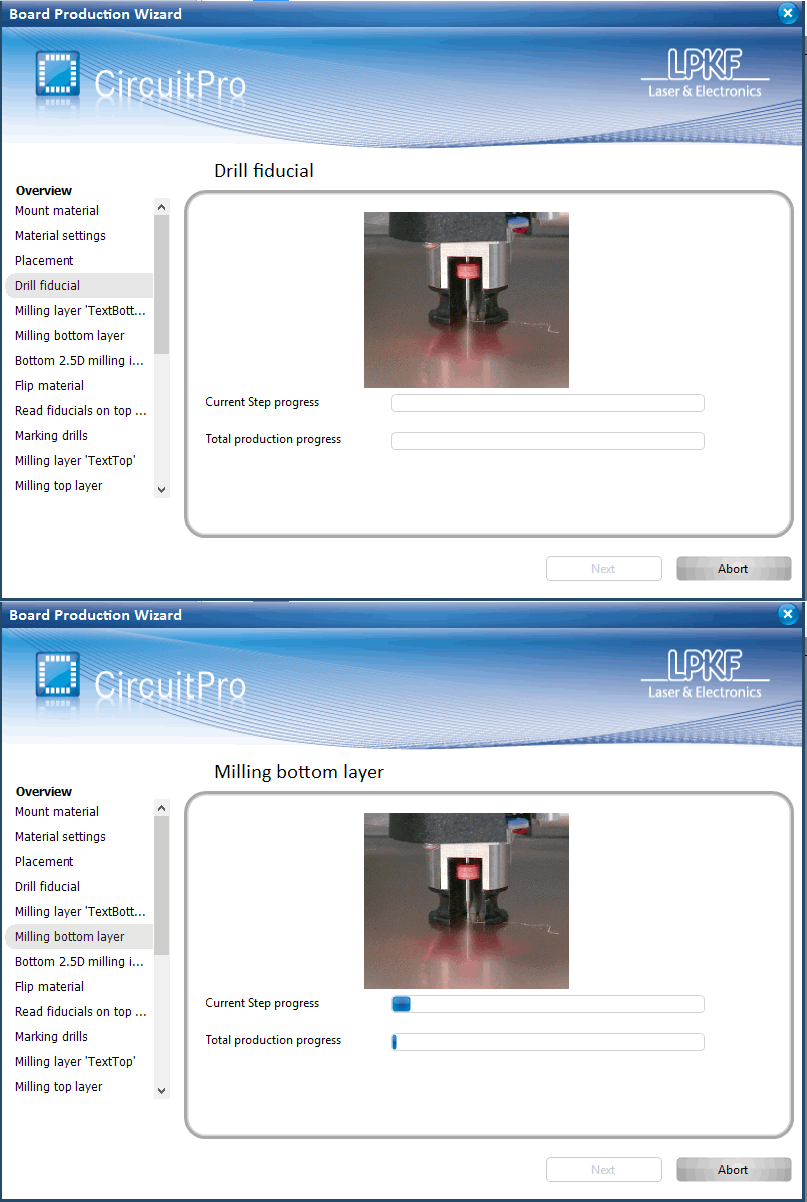
Once the placement of the design has been decided, the milling machine proceeds to 'Drill Fiducials', 'Mill the bottom layer' and 2.5D insulation milling. You can view the milling progress via the 'Machining View'. |
|
Once the milling for the bottom layer is complete, the machine will prompt to open the milling machine's enclosure lid in order to flip the board along it's symmetry axis. |
|
When the enclosure lid is closed, confirm it by accepting the pop-up dialog. Next the milling unit will attempt to locate the fiducial markings and re-align the design (Top Layer) in the machining view with the locations of the physical markings. |
|
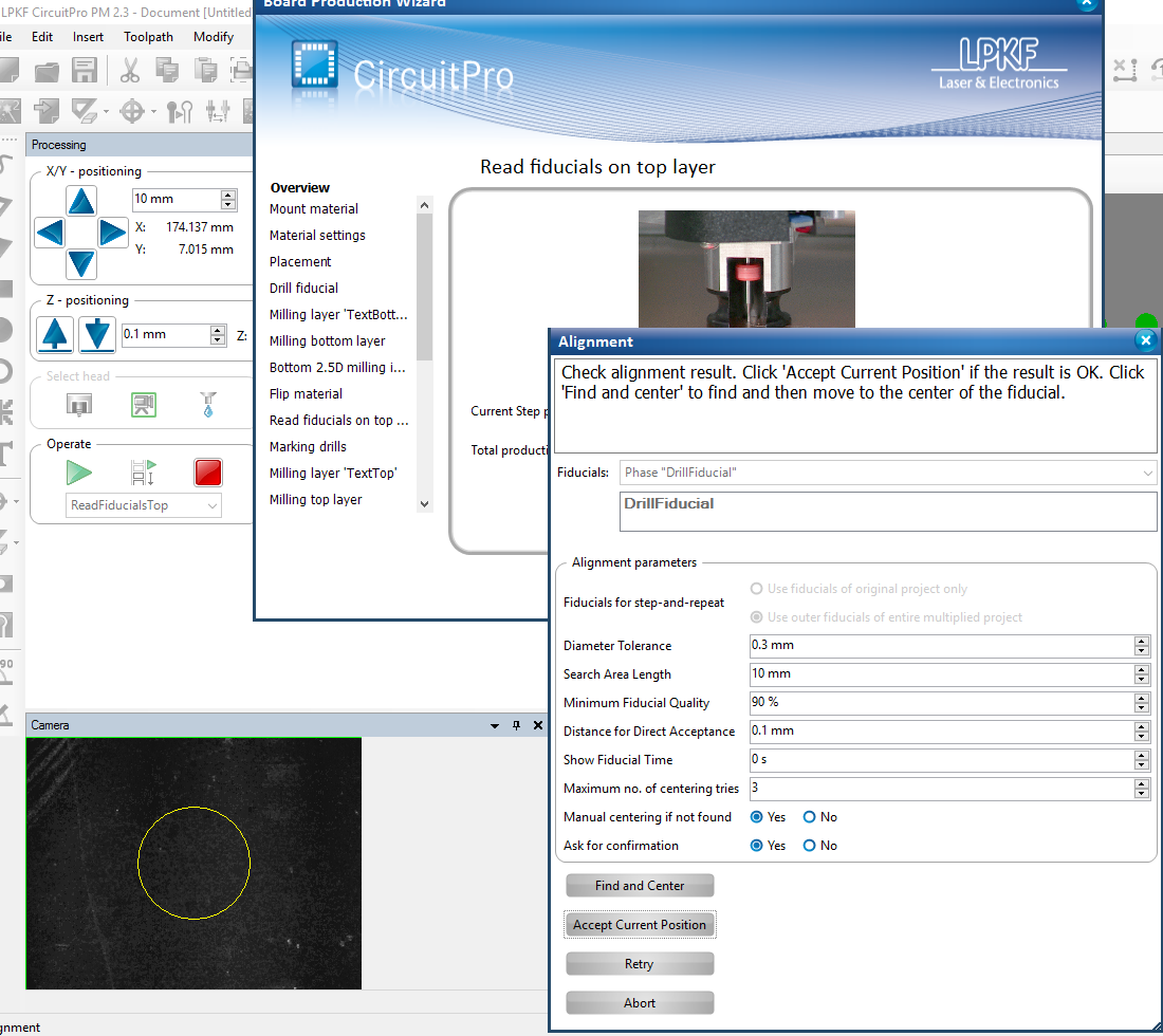
Most often, the milling head will not be able to locate the fiducial markings (due to a mismatch between the initial board alignment and the alignment after flipping the board). If the the milling head is not able to find the fiducial marking, the Alignment dialog will present options to adjust alignment parameters, 'Find and Center', 'Accept Current Position', 'Retry' or 'Abort' the board production process. |
|
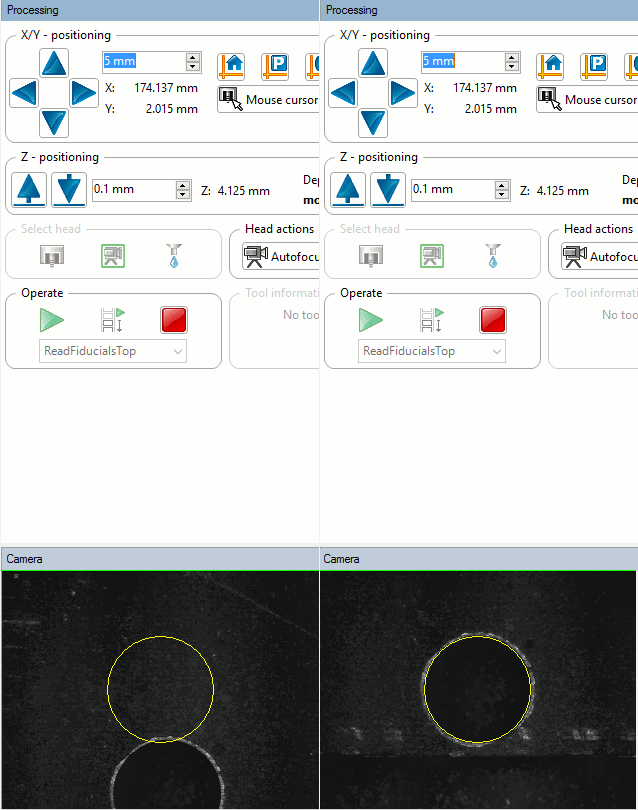
Utilize the milling head navigation buttons in the 'Processing Panel' to move it and locate the fiducials manually. Ensure that the camera head icon is active under the 'Select Head' section. |
|
Once all the fiducials have been located, the milling machine movies into the next phase where the via hole center are marked. After this, the top layer is milled and the contour along the design outline is routed. This process takes anywhere between 10 minutes up to 2 hours, depending on the design milling area and its complexity (more vias). |
|
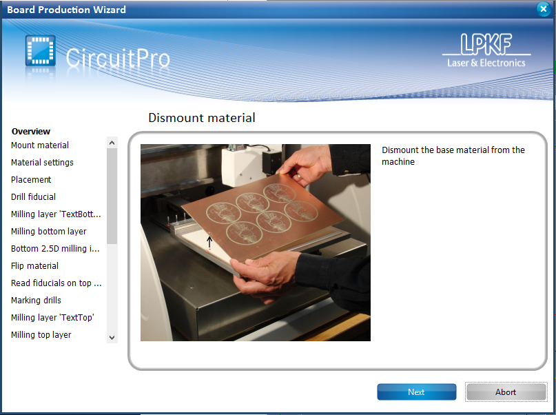
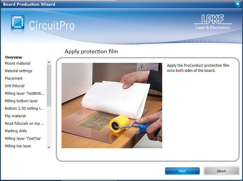
After the top layer has been milled, the machine prompts to dismount the copper board from the vacuum table top. This is to ensure that ProConduct Protection film has been applied over the top and bottom layers of the design. Open the enclosure lid and dismount the copper board (Save the paper tape for later use). |
|
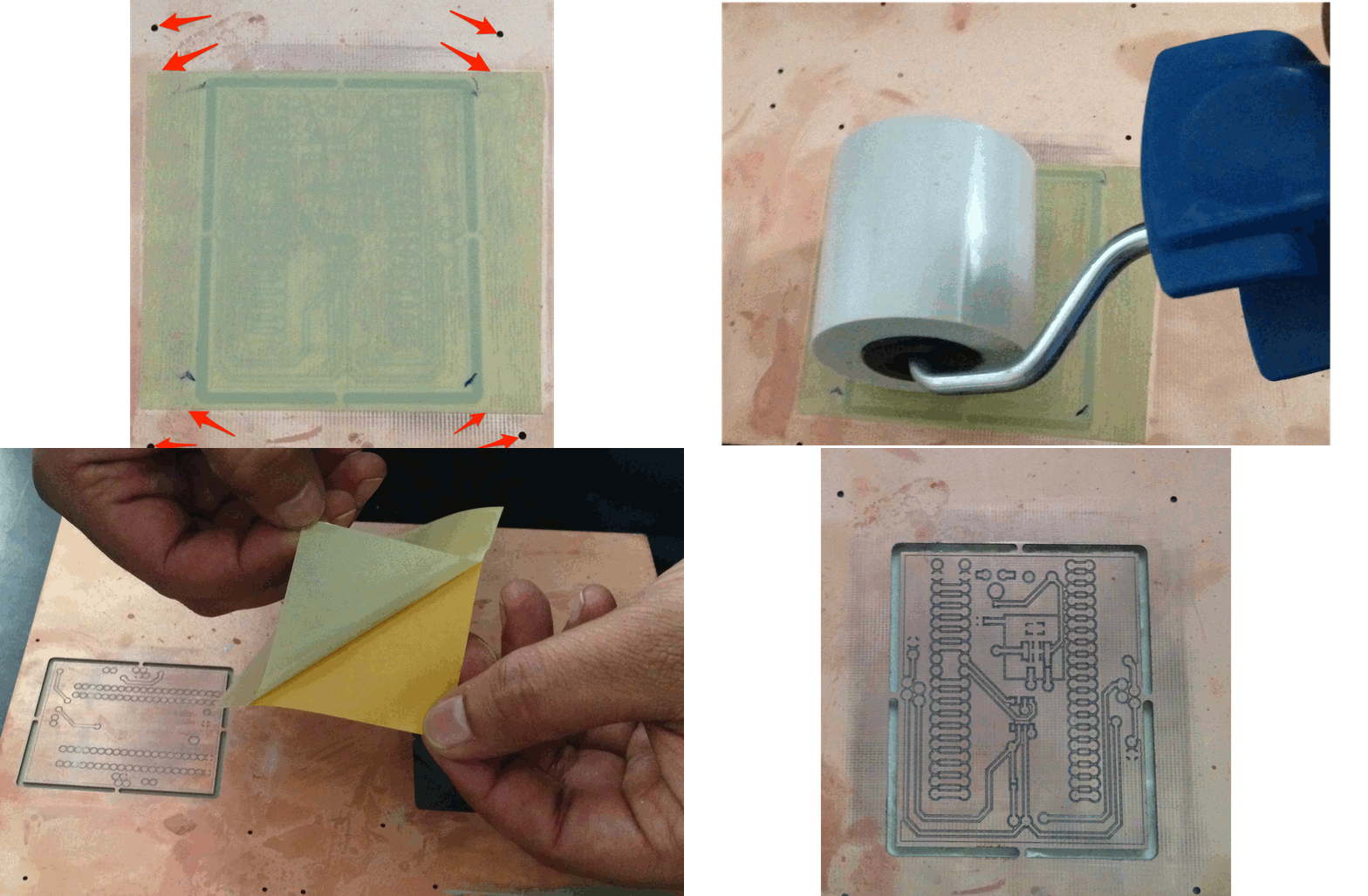
If your design does not cover the entire region of the copper board, you will need to cut out sections of the protection film. Size the cut outs to match the outline of the design. |
|
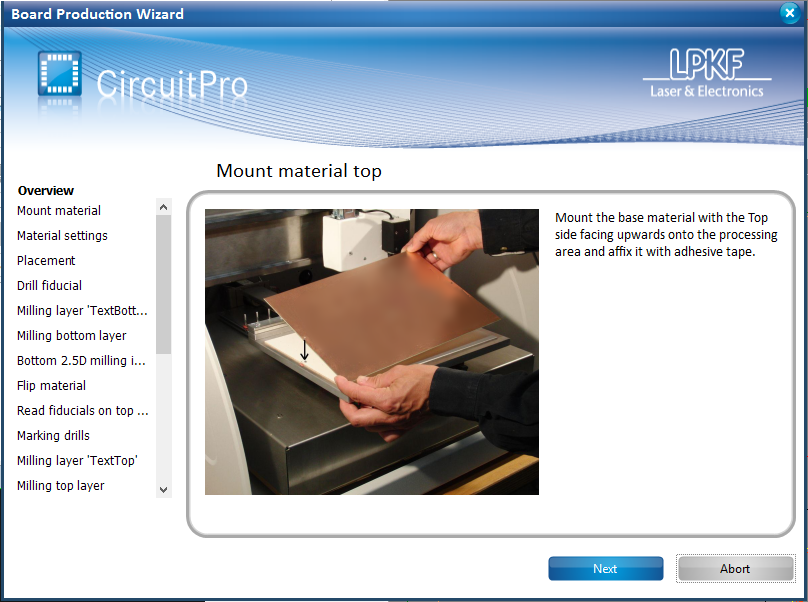
Mount the board with protection film onto the vacuum table and affix it firmly with paper tape. Close the enclosure lid and confirm it on CircuitPro. The milling machine will now search for fiducial marking to align the design with the actual location of the board. Use the processing panel as outlined earlier to manually locate the markings if required. |
|
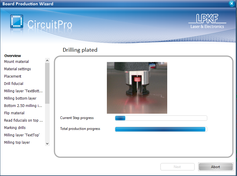
Once the fiducials are identified, the milling machine proceeds to drill the via holes. This procedure takes anywhere between 5 minutes and 1 hour depending on the complexity of the design (number of vias). |
|
When the drilling process is complete, CircuitPro prompts for a board dismount and the rest of the board production process is to be performed manually. |
|
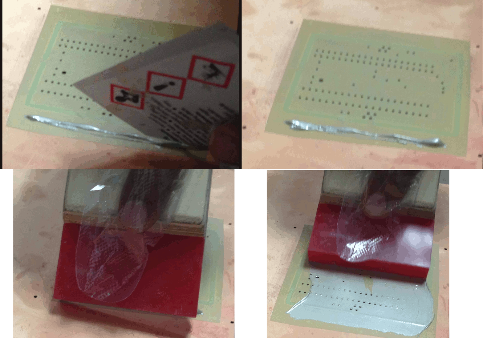
Wear disposable gloves before applying the ProConduct paste. Choose a flat surface to place the board. Place the 'Backing sheet (Absorbent fleece)' below the copper board so as to absorb any paste that may flow through the board down to the surface. |
|
After the paste has been satisfactorily applied, switch the 'Air Management System' to standby and dismount the copper board and Backing sheet from the vacuum table. |
|
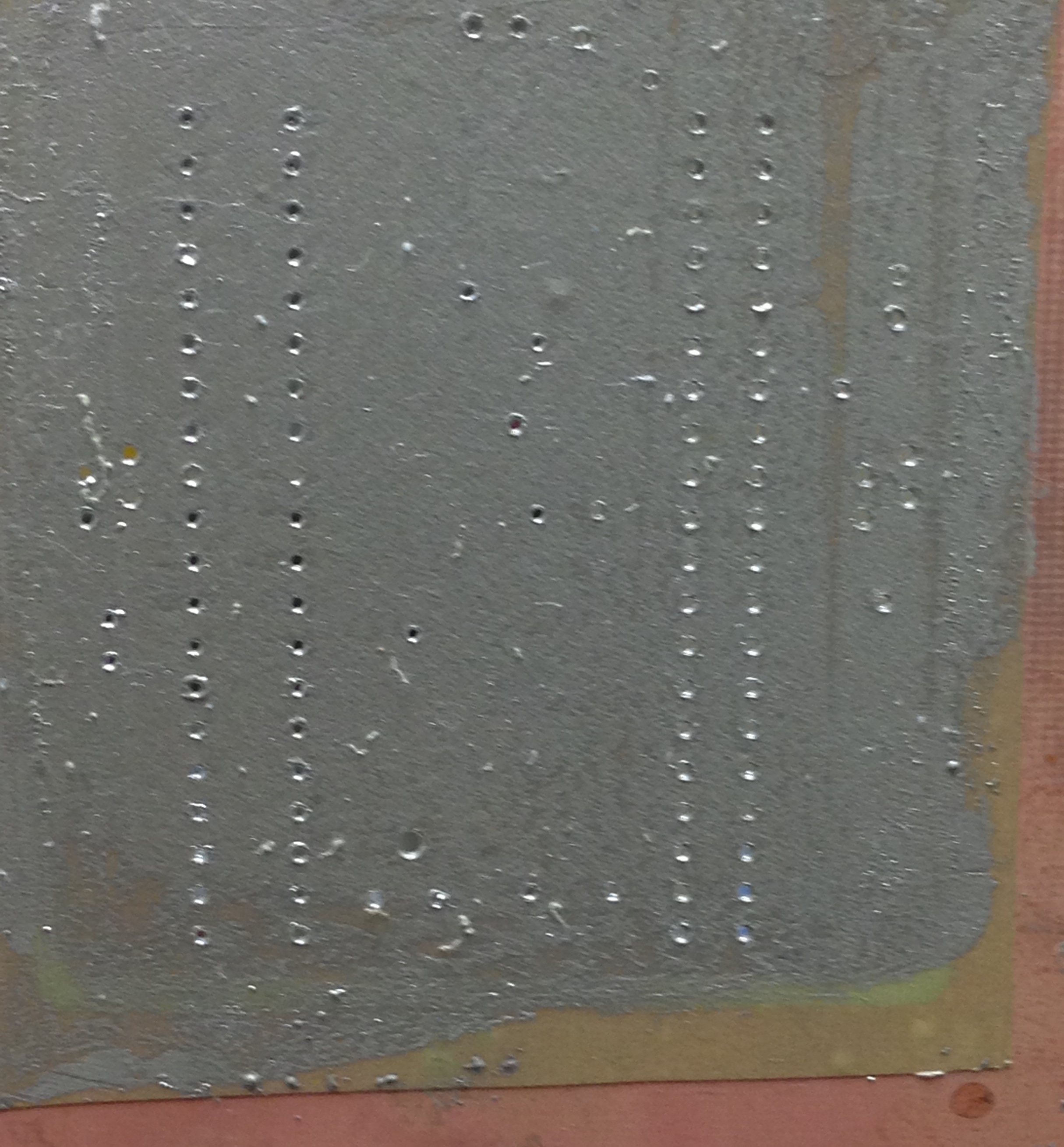
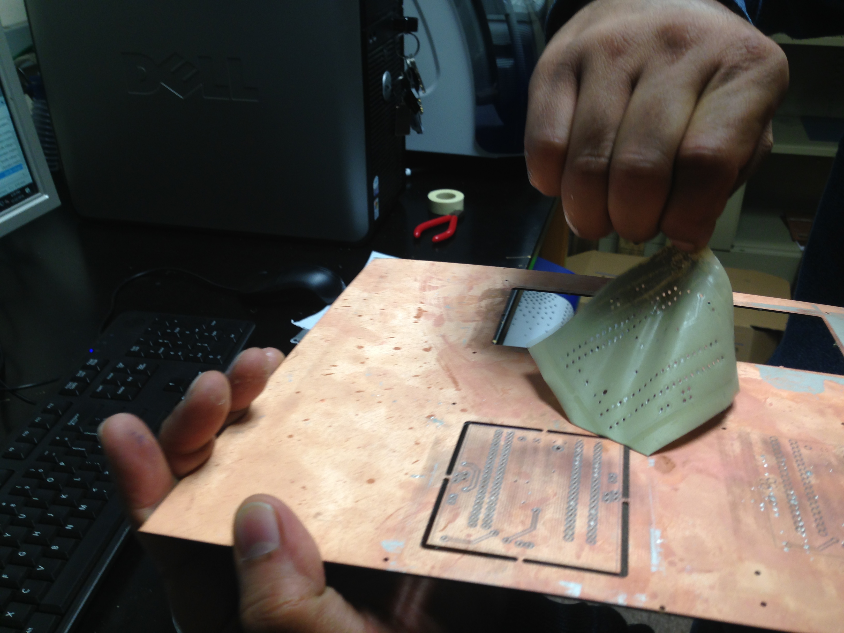
Dispose off the gloves and peel off the protection film before placing the board in the oven. Do not attempt to clean off any excess ProConduct at this stage. |
|
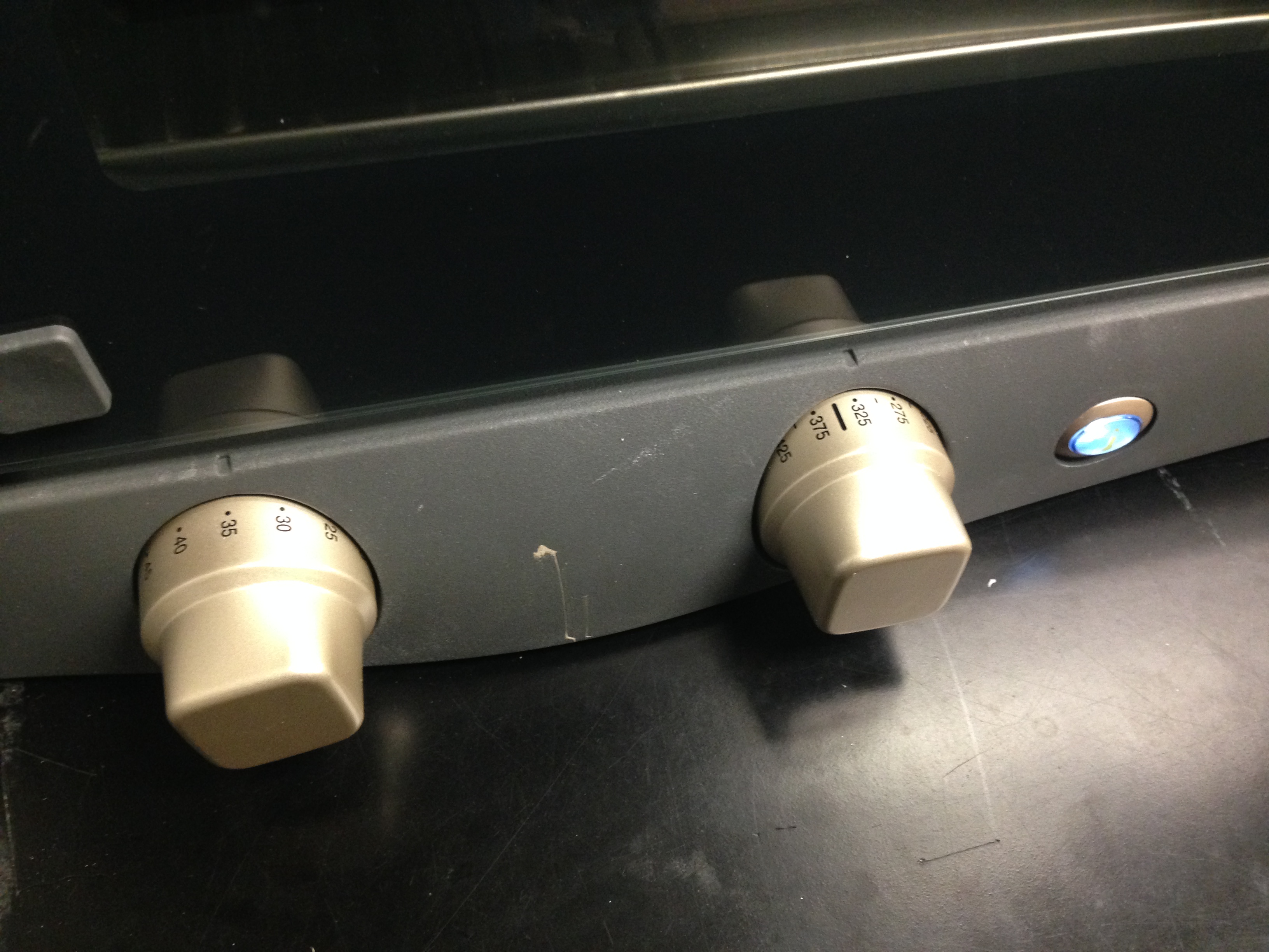
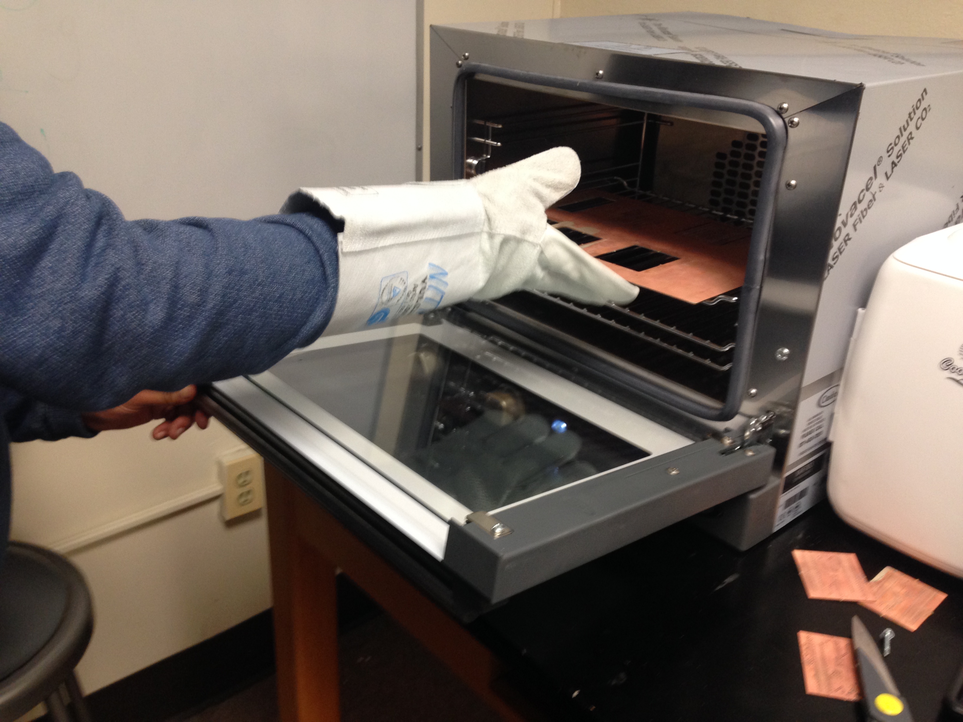
Wear heavy duty gloves before opening the oven. Place the board in the oven (preferably the center rack) and close it. Set the oven to heat up for 30 minutes. |
|
Board Cleanup and Safe Shutdown
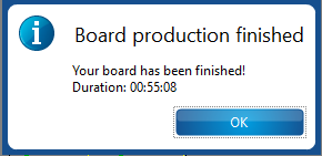
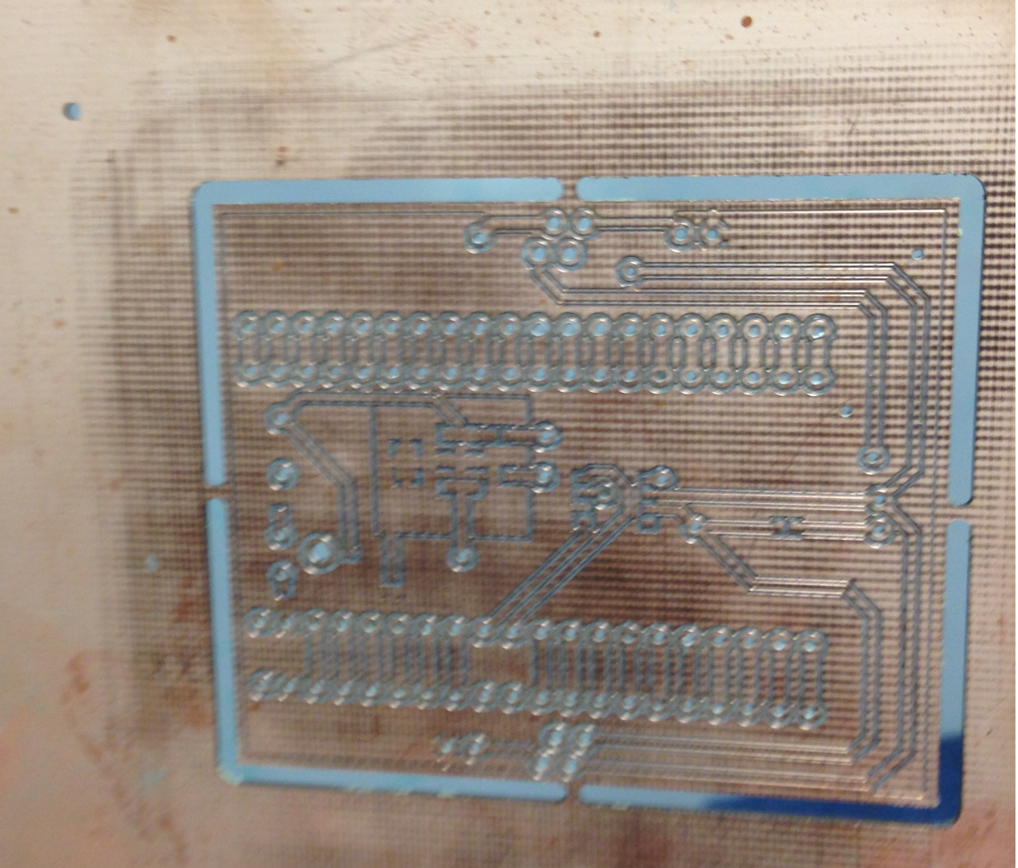
Confirm the prompt from CircuitPro to complete the board production process. A sample board is shown for illustrative purposes. |
|
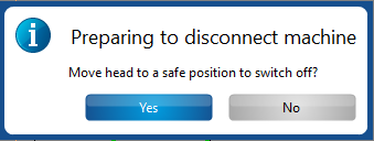
Click on 'File->Exit' to close CircuitPro. CircuitPro prompts the user for moving the milling head to a safe position (This position is randomly assigned). Switch off the milling machine and ensure that the enclosure lid is firmly shut. |
|
Information regarding consumables (size and thickness)
# |
Description |
Qty. |
1 |
FR4 double-sided ½ oz. copper clad base material 12” x 9” x 39 mil (Part# 119574) |
10 |
2 |
Single Sided laminate material for outer layers, ⅛ oz. Cu w/ protection foil. 12” x 9” x 8 mil (Part# 119571) |
20 |
3 |
Prepreg bonding material. 12” x 9” x 6 mil (Part# 119572) |
40 |
4 |
Pressing cardboard cushion 12” x 9” x 26 mil (Part# 119573) |
4 |
Material Settings and ProConduct paste Usage
For all board types, the best settings and ideal ProConduct paste usage is listed below. ProConduct paste is expensive and must be used conservatively.
Apply ProConduct paste only on one side of the board on top of LPKF's protection film after the drilling stage.
Board Type |
Board Dimensions |
Specified Thickness |
CircuitPro Material Settings |
Amount of ProConduct Paste |
Single-Sided Flexible Copper Board (Laminate) |
12" x 9" |
0.008" (8 mil) |
Copper Thickness (µm) = 9 |
2 Packs (One side) |
Double-Sided Copper Board |
12" x 9" |
0.039" (39 mil) |
Copper Thickness (µm) = 18 |
3 Packs (One side) |
Double-Sided Copper Board |
10" x 8" |
0.032" (32 mil) |
Copper Thickness (µm) = 18 |
3 Packs (One side) |
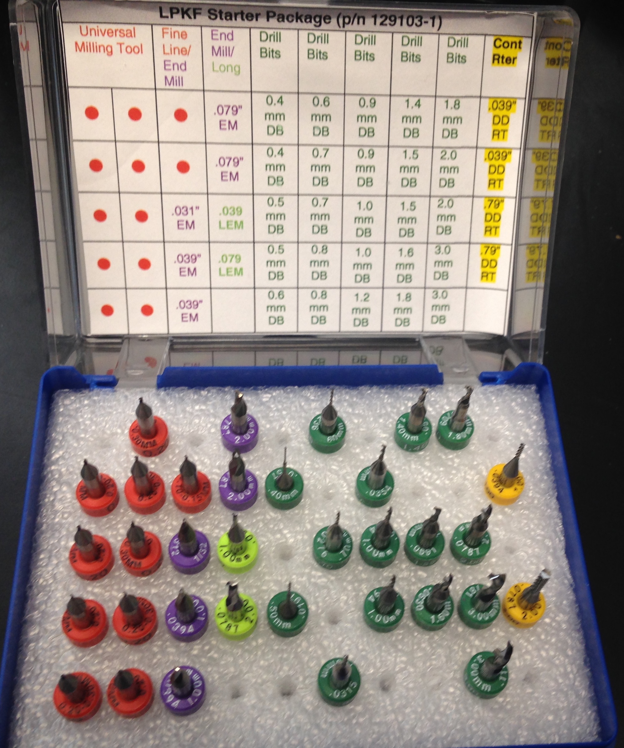
LPKF starter package drill bits (Part# 129103-1)
Drill Type |
# |
Size |
Qty. |
Universal Milling Tool |
1 |
0.20 - 0.30 mm |
10 |
Fine Line |
1 |
0.10 - 0.15 mm |
2 |
End Mill |
1 |
0.79 mm (0.0311") |
1 |
2 |
1.00 mm (0.0394") |
2 |
|
3 |
2.00 mm (0.0787") |
2 |
|
Long End Mill |
1 |
1.00 mm (0.0394") |
1 |
2 |
2.00 mm (0.0787") |
1 |
|
Drill Bits |
1 |
0.40 mm (0.0157") |
2 |
2 |
0.50 mm (0.0197") |
2 |
|
3 |
0.60 mm (0.0236") |
2 |
|
4 |
0.80 mm (0.0276") |
2 |
|
5 |
0.90 mm (0.0315") |
2 |
|
6 |
1.00 mm (0.0394") |
2 |
|
7 |
1.20 mm (0.0472") |
1 |
|
8 |
1.40 mm (0.0551") |
1 |
|
9 |
1.50 mm (0.0590") |
2 |
|
10 |
1.60 mm (0.0629") |
1 |
|
11 |
1.80 mm (0.0708") |
2 |
|
12 |
2.00 mm (0.0787") |
2 |
|
13 |
3.00 mm (0.1181") |
2 |
|
Contour Router Bits |
1 |
1.00 mm (0.0394") |
2 |
2 |
2.00 mm (0.0787") |
2 |
RF starter package drill bits (Part# 116394-1)
Drill Type |
# |
Size |
Qty. |
End Mill |
1 |
2.00 mm (0.0787") |
2 |
Long End Mill |
1 |
2.00 mm (0.0787") |
2 |
Drill Bits |
1 |
0.15 mm (6 mil) |
3 |
2 |
0.25 mm (10 mil) |
5 |
|
3 |
0.39 mm (15.7 mil) |
3 |
Maintenance
Exchanging drill bits
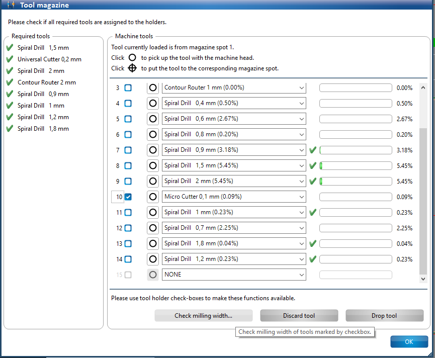
If a new drill bit needs to be affixed to an empty slot/clamp, choose the position in CircuitPro. If there is no drill bit present at the chosen position, it will be specified as 'NONE'. |
|
Use the drop down menu to assign a new drill bit to the position. Select the drill bit and manually affix it onto the tool clamp behind the tool magazine. |
|
Take extreme care when affixing a new drill bit or removing one to/from their respective tool clamp. The drill bit clamps onto two positions above and below its distance ring. |
|
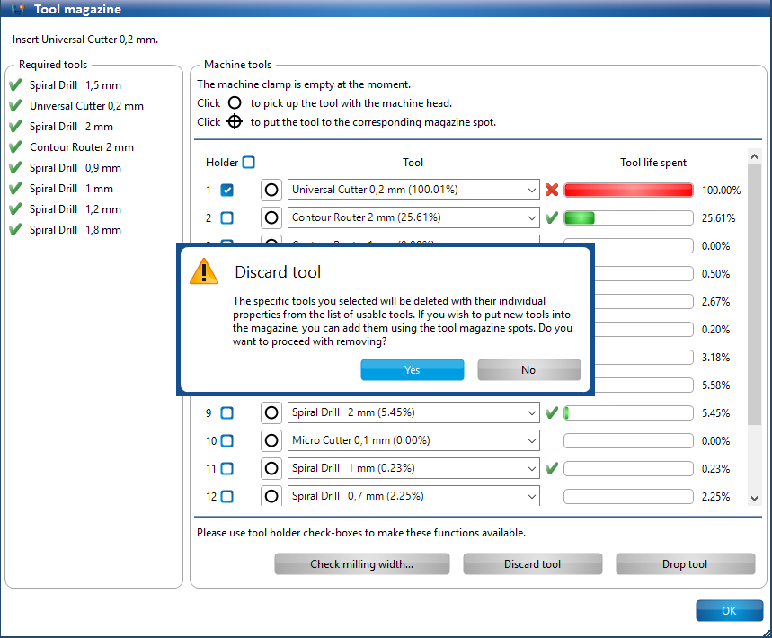
When a drill bit has reached its end of life, select the 'Tool Magazine Selection' option and check out the 'Holder' box beside the expired drill bit. The 'Discard Tool' option will be highlighted. |
|
Click on 'Discard Tool' and select 'Yes' in the pop-up dialog prompt. Open the milling machine's enclosure lid to manually remove the drill bit. |
|
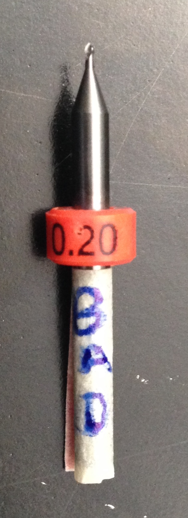
Do not forget to label expired drill bits. Use a paper tape mark the expired drill bit appropriately. |
|
Collet Cleaning
The milling head collet must undergo periodic maintenance depending upon the intensity of the workload (as often as after milling every ten boards).
The cleaning process is explained in the video below.
Collet_Cleaning.mp4
