- Any communication signal must occupy a finite bandwidth.
- Nyquist showed (in 1924) that if signal has V discrete levels, then
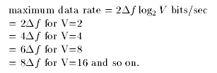
V must increase exponentially for a linear increase in the data rate.
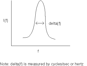
- The rate at which signal levels change is the baud rate.

- One cannot distinguish arbitrarily close voltages because any real communication channels has noise. Shannon showed (in 1948) that

- Nyquist showed (in 1924) that if signal has V discrete levels, then
- The bandwidth of a medium is limited ot its carrier frequency; so, it is advantageous to use higher carrier frequencies to transmit higher data rate signals.
The radiation that carries signals can be guided or un-guided.
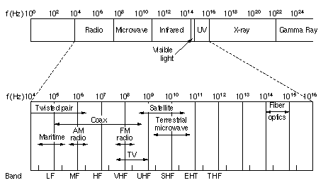
Fig. 2-1. The electromagnetic spectrum and its uses for communication.
- Guided Waves
- twisted pair (used in telephones and have a very low data rate)
- coaxial cable(used for computer connections; cable tv)
- fiber optics (used for high data-rate trunks in telecommunications systems) [Note the big gap between the central frequency of optical fibers and everything else.]
Videophones and other high-speed communications over phones are not possible at high quality because the bandwidth of twisted pair.
Where do we go?
- coaxial cable [owned by cable tv companies-- and they can sell phone service too, maybe]
- fiber to the home [expensive but would deliver almost in finite bandwidth]
- fiber to the curb [with twisted wire or coax to the home, the bandwidth would be significantly increased at a reasonable cost.]
- Unguided Waves
- radio, tv, sattelite, microwave
- As the frequency increases, the waves become less capable of going around obstacles and through buildings. [They are less wave-like and more particle-like.]
- The switch-over point is at about 100 Mhz--1Ghz.
- Guided Waves
- Why study the telephone network?
- It is the network "par excellence" connecting people in places all over the world.
- A large amount of computer communication is done over the phone system via modems. A dialup connection has one error in every 10^5 bits (with a maximum data rate of 10^4 bits/sec), so dealing with the phone system's limitations is important as well.
- Connecting everyone directly is impossible because too much wiring is required. (With n users, there would be n! connections!).
The system developed from completely connected -> connected through swithcing offices -> 5-level hierarchy (at AT&T before breakup).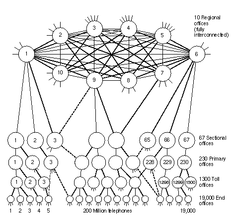
Fig. 2-2. The AT&T telephone hierarchy. The dashed lines are direct trunks.
- Each telephone is connected by twisted wire through the local loop to the end office.
End offices are connected to switching centers called toll offices or tandem offices (if they are in the same local area) by toll connecting trunks.
Toll offices are connected to higher levels via intertoll trunks.
- Connections are made at the lowest possible level of the tree. Also, there are some special, direct links for very busy paths (New York to Los Angeles).
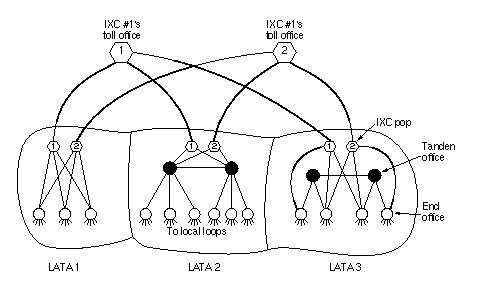
Fig. 2-3. The relationship of LATAs, LECs, and IXCs. All the circles are LEC switching offices. Each hexagon belongs to the IXC whose number is in it.
- In 1984, AT&T was broken up into one long-distance company and 7 RBOC's (Regional Bell Operating Companies).
The United States was divided into 160 LATA's (Local Access and Transport Areas). In most LATA's there is one LEC (Local Exchange Carrier), but there can be several (there are more than 1500 independent carriers in the US).
Long-distance companies (called Inter-eXchange Carrier = IXC) carry traffic between LATA's. Each can build a switch in any LATA where it wants to carry traffic called a point-of-presence (POP) which is connected to the tandem office or the end offices.
- In 1995, things were organized again to allow even more competition.
- Each telephone is connected by twisted wire through the local loop to the end office.
- Analog-to-Digital Conversion
- All local loops are analog (twisted pair).
- Almost all trunks are digital (microwave or optical fiber)-- but some are still analog.
- Digital links cost less and have higher fidelity. (The issue is replacing current analog links).
- Since local loops are analog, one must take a digital computer signal, turn it into analog at the loop (via a modem), then turn it digital again (via a codec) at the end office.
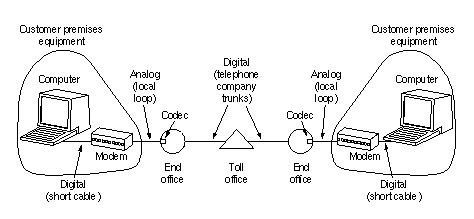
Fig. 2-4. The use of both analog and digital transmission for a computer to computer call. Conversion is done by the modems and codecs.
- Modems
- Information is transmitted by modulating a sine wave carrier between 1,000-2,000 Hz.
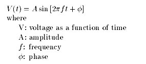
Fig. 2-5.
One can transmit information by altering:- amplitude (AM=amplitude modulation)
- frequency (FM=frequency modulation)
- phase (PM=phase modulation)
- The basic line rate (baud rate) is 2400. To get higher data rates, one can use a combination of phase and amplitude modulation. Using an appropriate combination of phases and amplitudes, it is possible to raise the bit rate. The pattern on the left (ITV V.32) corresponds to 9600 bps.
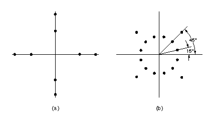
Fig. 2-6. (a) 3 bits/baud modulation. (b) 4 bits/baud modulation.
- To get higher data rates, it is possible to use a variety of sophisticated error correction and data compression schemes.
- Information is transmitted by modulating a sine wave carrier between 1,000-2,000 Hz.
- Multiplexing
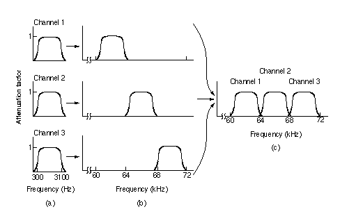
Fig. 2-7. Frequency division multiplexing. (a) The original bandwidths. (b) The bandwidths raised in frequency. (c) The multiplexed channel.
- Old analog trunks multiplex different conversations (channels) together using FDM (Frequency Division Multiplexing). Voice channels each occupy 4Khz (3Khz for data and 500Hz on each side as a guard band). 12 channels = group; 5 groups = supergroup; 5 or 10 supergroups = mastergroup
- Digital trunks use TDM (Time Division Multiplexing).
- The incoming signal is sampled in a codec (coder-decoder) at 8000 samples per second
(125 µ sec/sample) which is the Nyquist limit. - In the United States: Each sample produces 7 bits of data (corresponding to 2^7 = 128 amplitude levels) and one additional bit that is used for control for a total of 8 bits. Twenty-four channels are combined with eight bits per channel to make a T1 or DS1 frame. One additional bit is used at the beginning of the frame for synchronization in the pattern 101010...
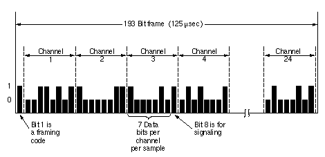
Fig. 2-8. The T1 carrier (1.544 Mbps).
- The T1 streams are time-multiplexed together, along with extra framing and recovery bits to form successively higher and higher data rate channels.
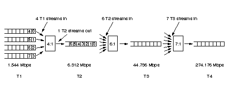
Fig. 2-9. Multiplexing T1 streams onto higher carriers.
- This is the North American Digital Hierarchy. Other schemes are used elsewhere (see Tanenbaum).
- The incoming signal is sampled in a codec (coder-decoder) at 8000 samples per second
- SONET/SDH (Synchronous Optical NETwork/Synchronous Digital Hierarchy)
- Different US IXC's had different, proprietary optical TDM systems to connect to fibers--not to mention the European and Asian systems. To make things uniform, Bellcore (the RBOC's research arm--just sold to SAIC) developed SONET. CCITT came up with the SDH standard which is compatible.
- Design goals:
- Standardize all carriers world-wide.
- Access individual channels without completely demultiplexing the data stream.
- A straightforward path to Gbit/sec systems.
To do that, the system is synchronous--controlled by a master clock to one part in 10^9. This level of synchronism is only feasible in optical fibers!
- A SONET system has repeaters and multiplexers between the source and destination.
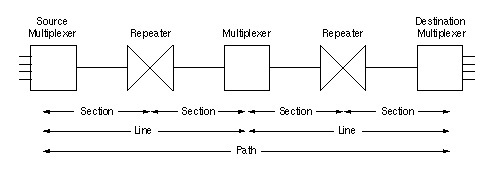
Fig. 2-10. A SONET path.
Path = source-to-destination link; Line = multiplexer link; Section = repeater link; A repeater is where information is electronically regenerated. - SONET frames are transmittted at 8000 frames/sec, corresponding to the rate at which voice channels are sampled. Each frame has 810 bytes (6480 bits) organized conceptually in 9 rows of 90 bytes each. The first three columns are for section overhead (the first three rows) and line overhead (the next six rows). The remaining 87 columns are for data. The gross data rate is 51.84 Mbps and the user data rate is 50.112 Mbps.
Note that the data can begin anywhere and can extend between frames. The data is referred to as the SPE (Synchronous Payload Envelope). Its first column is the path overhead. The flexibility is very important in dealing with ATM.
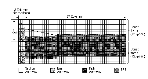
Fig. 2-11. Two back-to-back SONET frames.
- The multiplexing of multiple data streams, called tributaries, are important in SONET.
The base rate is STS-1 (electrical) or OC-1 (optical). The tributaries are byte-interleaved, not bit-interleaved, so the channels are separable. THERE IS NO ADDITIONAL OVERHEAD. So, the rate of STS-3 = 3*STS-1.
- The base level of SDH (referred to as STM-1) corresponds to STS-3 or OC-3 and runs at 155.52 Mbps. The levels of SONET are multiplexed in multiples of 3 for compatibility with SDH.
OC-3c (where "c" is for concatenated) means that there is a single data stream, rather than 3 multiplexed together. The OC-3c channel is the basic transport vehicle for ATM.
- Optical WDM
At rates higher than OC-48 (2.56 bits/sec) physical effects in the fiber make it hard to transmit TDM signals over long distances. To reach higher data rates and to use optics in networks, OC-48 channels at different wavelengths are multiplexed. Systems using this approach are just now evolving.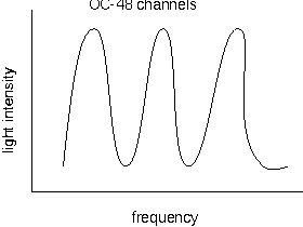
Fig. 2-12.
- Switching
- Circuit-switching vs. packet-switching
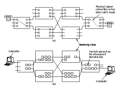
Fig. 2-13. (a) Circuit switching. (b) Packet switching.
- In a circuit-switched network, a physical layer, hard-wired connection is set up before the communication can begin. (It may be copper, fiber, sattelite, or a combination.) Thus, there is a delay before data transmission, but afterward, transmission is continuous. This is good for voice but bad for data.
Note: A circuit-switched network is necessarily connection-oriented at all layers (to the extent that it makes sense to speak of layers in this case--another issue).
- In a packet-switched network, the packets contain much if not all of the routing information.
Transmission can begin immediately and be connectionless as in IP or Transmission can be connection-oriented and sequential, requiring setup, as in ATM. Note: It is the flexibility of this approach that makes data and voice in one network possible.
- In a circuit-switched network, a physical layer, hard-wired connection is set up before the communication can begin. (It may be copper, fiber, sattelite, or a combination.) Thus, there is a delay before data transmission, but afterward, transmission is continuous. This is good for voice but bad for data.
- Switching Architectures
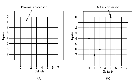
Fig. 2-14. (a) A crossbar switch with no connections. (b) A crossbar switch with three connections set up: 0 with 4, 1 with 7, and 2 with 6.
- The simplest switch conceptually is a crossbar switch. A switch with n inputs and n outputs has n^2 possible connections, referred to as crosspoints. This switch is non-blocking since every possible connection can be made simultaneous but requires many possible connections.
- By splitting the switch into stages, it is possible to build space-division switches with far fewer crosspoints. With N inputs and crossbars with n inputs, we need N/n input crossbars and N/n outputs. The second stage has k N/n x N/n crossbars.
What is the number of crosspoints? 2(N/n)nk + k(N/n)^2 = 2kN + k(N/n)^2. With N=1000, n=50, k=10, Number of crosspoints = 24,000. But: the switch can block! As usual, it is an optimization problem.
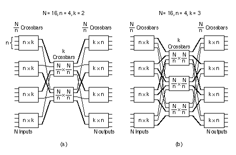
Fig. 2-15. Two space division switches with different parameters.
- Time-division switches use time slot interchangers to carry out a similar operation in time.
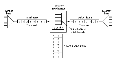
Fig. 2-16. A time division switch.
- ISDN, B-ISDN, and ATM
- ISDN (Integrated Services Data Network) began in 1984 when the world's phone companies met under the auspices of the CCITT to plan end-to-end digital services.
- Enhanced voice services with direct links to computers are possible (when a customer calls a stockbroker, his portfolio could become available on the computer at the same time).
- A basic rate ISDN channel (also referred to as N-ISDN service) contains two 64-Kbps PCM channels for voice or data and a 16-Kbps channel for out-of-band signalling.
- This service is growing slowly. There isn't enough bandwidth to allow for video or a large enhancement of services, but it is MUCH better at 144-Kbps in connecting to the Intenet from home, and it is affordable.
- B-ISDN (Broadband ISDN)
- This technology is based on ATM which is packet-switched and transmitted at 155-Mbps (STS-3 = STS-1).
- Installing B-ISDN is a long-term, costly prospect because it requires replacing the local loops which cannot handle 155 Mbps. It also means replacing the current telco space and time division switches which cannot handle packet switching.
- Virtual Circuits are used to route packets (ATM cells). When a route is chosen through a network, entries are made in router tables so that when a cell with an appropriate header comes along it is sent along the correct path. Resources can also be allocated. The arrival rate depends on the application; data can be bursty while voice is smooth (allowing both), but sequence must be preserved.
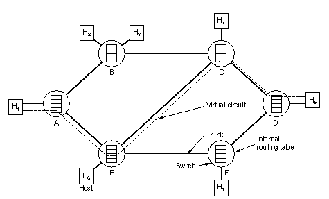
Fig. 2-17. The dotted line shows a virtual circuit. It is simply defined by table entries inside the switches.
- Building switches that:
- rarely drop cells
- never reorder cells
- How do we deal with contention when several inputs want the same output?
General principle: Output queuing is more efficient than input queuing. Tanenbaum discusses several switch designs that use output queuing based on this principle.
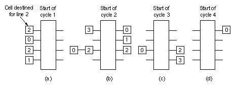
Fig. 2-18. Input queueing at an ATM switch.
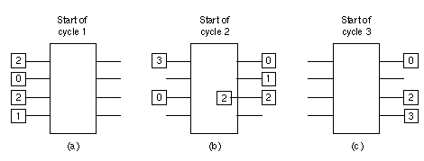
Fig. 2-19. Output queueing at an ATM switch.
- ISDN (Integrated Services Data Network) began in 1984 when the world's phone companies met under the auspices of the CCITT to plan end-to-end digital services.
- Circuit-switching vs. packet-switching