Lab 7
Objective and Overview
The purpose of this experiment is to understand how hazards occur and how they can be mitigated by
logic-design/switching-expression level modifications to the logic-minimization methods.
Discussion and Theory
Static Hazard
First, verify that a timing hazard exists, using the (minimal/smallest)
switching-expression for the function: .
Do you see that is a logic-level realization of an if-then-else statement that any programming language must have?
(any prog lang must have 3 constructs: (1) sequential execution
(2) jump = unconditional branch and (3) Conditional branch which can also be used to
realize a jump).
The timing hazard will be eliminated by realizing this function as:
. Note that by the consensus theorem of Boolean Algebra;
(which appears as T9(a) in TeH list of 10 commandments from chapter 2);
.
In the previous lab, delays in logic gates were modeled using the syntax #1. By doing so, when an input changes,
the resulting cascading changes along the ensuing logic chain can be observed -- neither intermediate nets in a path
nor the outputs change instantaneously with the input. This has implications for the
correct operation of combinational circuits -- they need time to reach a final result. This means that when any input changes, a certain time must be allowed for the combinational circuit to prepare a new final answer. This is called the combinational path delay. Once an input changes, the output should not be sampled until this amount of time has elapsed
(ex: the long carry-chain in a 32-bit addition).
A result of combinational delay is that in the process of computing a new answer, the output and intermediate nodes may momentarily take on values that are neither the new final nor the previous (i.e. previous to the input change)
answers/outputs/values. This means that for a complex combinational circuit if the previous result was 1 and the resulting output of the new input is also 1, there may still be a 0 that occurs momentarily at the output. This behavior is known as a static-1-hazard, and can occur with certain input changes.
Our focus is on changes of one input in a combinational circuit and how to eliminate hazards.
There are two types of static hazards, as shown below in the image:
- Static 1-Hazard: If the output is currently at logic state 1 and after the input changes its state, the output momentarily changes to or toward 0 before settling back on 1, then it is a Static-1 hazard.
- Static 0-Hazard: If the output is currently at logic state 0 and after the input changes its state,
the output momentarily changes toward 1 before settling on back at 0, then it is a Static-0 hazard.
In the SOP implementation (switching expression) of a function, if any pair of adjacent 1's (adjascent in the K-map)
is not covered by a common implicant (i.e. a product-term), then a static-1-hazard exists.
Accorrdingly,
- Step-1: Complete the K-map of
- Step-2: Identify all pairs of adjacent 1's
- Step-3: For every pair, if one single implicant in the switching expression
does not cover them both; then a static 1-hazard exists (for the input transition corresponding
to the variable that changes across the two adjacent squares in the K-Map).
Example – Consider the circuit and K-map shown below for the function
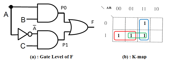
The implicant (product term) corresponding to the pair of 1’s encircled in green is not
included in the minimized switching expression .
Hence, a static 1-hazard exists and is observable when the input A changes from high to low (with B=1 and C=1).
(why a transition in the other direction i.e. A: 0-->1 does not cause a hazard?)
This is due to the fact that gate P0 changes to 0 before gate P1 changed to 1.
As a result, for a small amount of time, both P1 and P0 are low which in turn can cause the output to go
toward a low for a small time interval. Such temporary transitions are also known as glitches and are undesirable
(identify at least 2 potentially serious problems glitches can cause).
In this circuit the root cause of the hazard is the delay of the inverter.
In a physical circuit, instead of observing a constant 1 on the oscilloscope
when A changes from 1 to 0 (with B=1 and C=1), we observe a small output excursion from the ideal high voltage.
Such a
momentary fluctuation towards a result that is neither the old nor the new final value;
is the evidence of a logic hazard.
In the next image, measured from a physical circuit, the input A changed from 1 to 0, and previous output was 1 and the new final output is 1. However, a momentary excursion of the output voltage away from high before returning,
indicates the static hazard. Note the output scale is different here, the output might not reach a valid logic '0'
in a physical circuit.
Since the inverter delay is small compared to the other gates, the
glitch is small and the output doesn't always fully transition to 0.
Even so, an excursion away from a valid logic '1' voltage can cause serious problems.

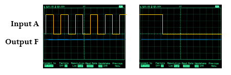
If in a classroom laboratory, the hazard can be more easily observed on an oscilloscope by continuously toggling the input A and seeing a repeated effect of the hazard manifested at the output. The result would look like this:

To avoid the glitch, we want F to have sufficient input states at all times during the transition to maintain the desired output during the transition.
Removal of static-1 hazard: Once detected, a static 1-hazard can be easily removed by introducing some more
terms to the switching-expression (i.e., adding gates to the circuit).
In above example the pair of 1’s encircled with green color causes the static-1 hazard.
To remove it, we just add the as a implicant (product-term) covering those two 1s to the existing
function as follows:
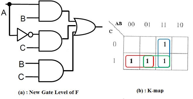
Implementing this function should eliminate the hazard. Now the output on oscilloscope would be a continuous high voltage.
Whereas 1-hazards are an issue in SOP, 0-hazards are an issue in POS.
(make sure u understand why this is the case).
The method to determine and resolve the static-0 hazard is similar.
For static 0-hazards we need to consider 0’s instead of 1’s.
If any pair of adjacent 0’s in the K-map are not covered by a common implicate (sum-term);
then a static 0-hazard exists.
Adding that implicate to the POS expression removes the static 0 hazard due to that
pair of adjacent 0s.
Verilog
The first circuit discussed can be described using the following structural description:
   not i1(a_n,a);

   and i2(p0,a,b);
   and i3(p1,a_n,c);

   or i4(f1,p0,p1);
Since delays are important to the hazard phenomenon, simple delays can be added like this:
   not #1 i1(a_n,a);

   and #1 i4(p0,a,b);
   and #1 i5(p1,a_n,c);

   or #1 i7(f1,p0,p1);
To cover the hazard, we'll introduce a new product:
and i6(p2,b,c);
We'll also introduce a three-input OR gate by including an extra input to the instantiations. Verilog primitives (e.g. OR (or),AND (and), XOR (xor)) support a variable number of inputs as follows:
or i8(f1,p0,p1,p2);
Below is the complete circuit covering the 1-hazard for the A transition from 1 to 0, including simple delays
   not #1 i1(c_n,c);
   not #1 i2(b_n,b);
   not #1 i3(a_n,a);

   and #1 i4(p0,a,b);
   and #1 i5(p1,a_n,c);
   and #1 i6(p2,b,c);

   or #1 i8(f1,p0,p1,p2);
Below is the full test. $display statements are like print statements, and are added here just to provide visual delineation in the printed output.
//Filename: hazard_test.v
module hazard_test;

   logic a,b,c;
   logic a_n,b_n,c_n,p0,p1,p2,f0,f1;

   not #1 i1(c_n,c);
   not #1 i2(b_n,b);
   not #1 i3(a_n,a);

   and #1 i4(p0,a,b);
   and #1 i5(p1,a_n,c);
   and #1 i6(p2,b,c);

   or #1 i7(f0,p0,p1);
   or #1 i8(f1,p0,p1,p2);


initial begin

   $monitor("%10t: f0=%b,f1=%b,p0=%b,p1=%b,p2=%b", $time,f0,f1,p0,p1,p2);
   $display("---------------------------------------------------------");
   a=1'b0; b=1'b1; c=1'b1;
   #1000
   $display("---------------------------------------------------------");
   a=1'b1; b=1'b1; c=1'b1;
   #1000
   $display("---------------------------------------------------------");
   a=1'b0; b=1'b1; c=1'b1;
   #1000
   $finish;

end

endmodule // hazard_test
To simulate using Icarus Verilog use the following commands at the command promp:
iverilog -g2012 hazard_test.v -s hazard_test
./a.out
Here is a result found in the printed output:
---------------------------------------------------------
         0: f0=x,f1=x,p0=x,p1=x,p2=x
         1: f0=x,f1=x,p0=0,p1=x,p2=1
         2: f0=x,f1=1,p0=0,p1=1,p2=1
         3: f0=1,f1=1,p0=0,p1=1,p2=1
---------------------------------------------------------
      1001: f0=1,f1=1,p0=1,p1=1,p2=1
      1002: f0=1,f1=1,p0=1,p1=0,p2=1
---------------------------------------------------------
      2001: f0=1,f1=1,p0=0,p1=0,p2=1
      2002: f0=0,f1=1,p0=0,p1=1,p2=1
      2003: f0=1,f1=1,p0=0,p1=1,p2=1
At time 2002, the glitch can be seen in f0, but not f1.
Supplemental Discussion for Advancement:
Since the logic glitch in this case is due to the delay of the inverter, making the other gates slower, e.g. #2, would make them not respond in the brief period that p0 and p1 are both low. However, in the physical circuit we might see the small excursion as seen in the earlier oscilloscope plots. In Verilog, changing the delay to #2 indicates that the gate will not output a new result that don't first persist logically for at least 2 time units, this is called inertial delay. Right now in this course, we are avoiding complicating matters with more Verilog concepts, but if you are interested in understanding further you can try the same experiment with other delays on the gates and see under which situations the hazard can be observed and in which it cannot. Regardless, the presence of a hazard in the logical structure is not defined by the delays -- a hazard-free implementation does not produce a glitch under any combination of delays.
Prelab:
- Perform the simulation of the hazard_test. Modify the code to produce a waveform file, vcd file and show the resulting waveform to the TA at the beginning of class.
- Convert the SOP to an POS.
- Identify transitions that can produce an observable 0-hazard and indicate an implicate term that can cover it
Lab Exercise:
The TA would normally provide 4-input expression at the beginning of the lab session, though this semester the selected express for is as follows:
- Complete the implementation
- Identify the hazards and input transitions
- Provide additional covering terms and provide the new function
- Perform simulation with and without the covering implicants
Lab Report and Grading
The following is the approximate grading distribution.
- The prelab will be worth 20%
- Lab Exercise 60% (completion based this semester, should be observable by the lab report)
- Completion of simulation for demonstrating glitches in the output
- Implementation of a hazard-free
- Completion of simulation for demonstrating glitch-free operation under the same transitions
- Lab Report (20%)
- Submit in the document the following (failure to submit may result in reduction of the Lab Exercise Grade)
- Verilog Code Listings if Separate from the Testbench
- Testbenches
- Drawings of and truth tables for the the circuits
- Waveform plots, with key features visible and annotated where possible
- Output listing (either from the screen or from a file)
- All the plots should be captioned. Mark axes with proper signal names. Tables should be properly titled, formatted, and captioned as well.
- Long code or output listings that are not appropriate to include inline with the text should be moved the appendix, though key portions of the code and listing should be included in the text where possible a reference to the listing in the appendix
- Comment and properly format the code that you include in the lab report.
- Testbenches should be included in the submission and must include the simulation control system task '$finish' , and be commented appropriately
- Include a very brief discussion on what is shown in each plot or table.
- Submit in the document the following (failure to submit may result in reduction of the Lab Exercise Grade)