Project 1: Slot Machine
This project is due on Monday, March 27, at 11:59:59 PM
(Eastern daylight time). You must use submit to
turn in your homework like so:
submit cs411_jtang proj1 proj1.circ proj1.txt [image1...]
Each submitted file must contain your name and assignment
number. For the Logisim file, place that information in a text label
on the main circuit. For the text file, place that information at
the top of the file. For image files, ensure your name and
assignment number appear somewhere in the image.
In this assignment, you will be building a circuit that implements a slot machine with four reels. The player "wins" if he can stop those reels so that they display "Prj1".
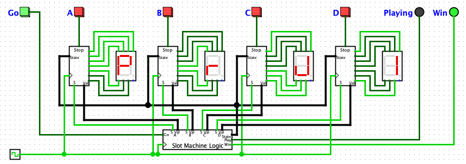
You will slowly build up each component in each part of this
assignment. Be sure to complete each section and test it thoroughly
before tackling the next part. This screenshot shows a fully working
project with the extra credit portion also implemented.
You will be reusing portions of this assignment for the remainder of this semester. It is in your best interest to design your circuits for maximum readability.
To begin, install the Logisim-evolution application. The program is written in Java and should run fine on Windows, macOS, or Linux; the instructor has tested this assignment on macOS against version 3.8.0. Logisim-evolution is a fork of the Logisim project. Logisim-evolution significantly improves upon Logisim and is better suited for this class; ensure you are using Logisim-evolution, not vanilla Logisim. One downside of Logisim-evolution is its lack of documentation. Work through Logisim's tutorial to get a feel for the interface. This assignment uses subcircuits extensively, so you should become familiar with that feature.
Part 1: Implement Reel Logic
To begin, create a directory for your assignment and download the following into that directory:
- https://www.csee.umbc.edu/~jtang/cs411.s24/homework/proj1/proj1.circ
- Skeleton circuits for this assignment.
Your first task is to implement the logic for each slot machine reel within Proj1_Reel. Each reel internally has a 2-bit counter to light a 7-Segment Display. When the counter's value is 0, show a P; for a value of 1 show a r; for a 2 show J; and for a 3 show 1.
Calculate seven Karnaugh maps, with each map corresponding
to a different display segment:
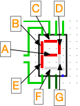
For each map, the input is the counter's value of 0, 1, 2, or 3. The
output of the map governs if that display segment should be shown (a
one) or not (a zero). Draw these Karnaugh maps as ASCII art, saved
to proj1.txt. Alternatively, draw them on physical paper,
take a snapshot, and upload the resulting images with the rest of
your files. For each map, be sure to label the axes and calculate
the sum of products. Also indicate which map corresponds to which
segment.
Then start filling in the Proj1_Reel subcircuit. In the
middle of this subcircuit add a counter; set that counter to 2 Data
Bits. Unfortunately Logisim-evolution's counter is difficult to
understand. Here are the ports needed for this project:
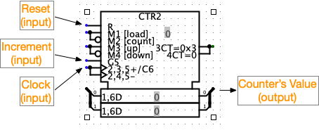
- Reset
- When set to 1, resets the counter to zero.
- Increment
- When set to 1 or when not connected, increment counter upon clock trigger. Will wrap the value around to zero.
- Clock
- Increment counter when clock phase goes from low to high.
- Counter Value
- Current value stored within the counter.
You are permitted to move input and output ports for this subcircuit and all subsequent subcircuits. Please do not rename any input or output ports, as that will make grading much more difficult.
Test your implementation so far. Go to the Proj1 subcircuit. Manually poke the Clock line. You should see all four reels rotate between P, r, J, and 1, in that order.
Part 2: Implement Game Logic
The next task is to design the Slot Machine game logic. Internally there is a state machine, with these four states:
- State 0: Idle
- In this state, the game is idle. Once the player presses the Go button, proceed to State 1.
- State 1: Initialize
- In this state, the circuit resets all internal values. Set all reels' counters to 0, and clear all reels' Stopped SR registers. If implementing the Extra Credit, also clear the Win SR register. After one clock cycle, proceed to State 2.
- State 2: Spin
- In this state, all reels are spinning. When the user presses a reel's Stop button, stop that reel. After all reels have stopped, proceed to State 3.
- State 3: Payout
- Nothing normally happens in this state. After one clock cycle, proceed to State 0. See the Extra Credit portion below.
Update Proj1_Reel. The State Input holds the 2-bit state value from above. The Stop Input is true when the user presses the stop button for that reel. Add a S-R Flip-Flop; call this the Stopped SR register. When the state is 1, reset the counter and Stopped SR. When the state is 2, if Stop input is 1 then set Stopped SR. Only increment the counter when in state 2, Stop is 0, and Stopped SR is 0. Route the value of Stopped SR to the Stopped output.
Then fill in the Proj1_Logic subcircuit. Add a 2-bit counter to hold the state. Increment that counter based upon Go, A_Stopped, B_Stopped, C_Stopped, D_stopped, and Clock inputs. Set Playing output to 1 whenever the state is not zero.
The inputs A_Val, B_Val, C_Val, D_Val and output Win are used by the Extra Credit portion.
Test this overall circuit. Enable Auto-Tick to get the full casino experience. (The instructor can consistently get the value Prj1 at 4 hertz or slower.)
Part 3: ULNAv2-C 16-Bit Adder
ULNAv2-C (UMBC's Limited Nifty Architecture, version 2 bugfix C) is the 16-bit RISC architecture that you will implement for this class's final project. In ULNAv2-C, all instructions are 16 bits and all data registers hold 16 bits. Internally all values are stored as big-endian.
There are 29 instructions defined in ULNAv2-C. Instruction numbers 6, 17, and 19 are undefined. Use the following links to obtain the full instruction set:
Download and read through the instruction set. Details will be provided in upcoming assignments. For this project, you will implement the ULNAv2-C ALU.
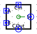
Take a look at the subcircuit adder_1bit. This 1-Bit (3,
2) Adder has three inputs, A, B,
and CIn (short for CarryIn). Its two outputs
are S (Sum)
and COut (CarryOut). This
implementation is one of many possible. Although it may not look
exactly like what you saw in earlier courses, its functionality is
identical. Then examine this subcircuit's appearance:
Fill in the adder_2bit subcircuit, that contains two instances of this 1-Bit Adder in a ripple-adder design. This subcircuit has three inputs: A (2 bits), B (also 2 bits), and CIn (1 bit CarryIn). Calculate the sum of A and B, and then collect the sum into a single 2-bit output S. Also add the output COut (1 bit CarryOut). You will need multiple splitters for this subcircuit.
Test your 2-bit Ripple Adder via the Poke tool, for a variety of inputs for A, B, and CIn.
In your proj1.txt file, calculate your gate propagation delays from when A, B, and CIn are set to when the final 2-bit S and the 1-bit COut are calculated. When calculating your delays, treat each gate, regardless of type, as 1 delay unit. For example, a AND gate has 1 delay unit. If that same AND gate's top input is inverted, the top path has 2 delay units, while the bottom path's delay is still only 1 delay unit. Therefore, the AND gate's output has a propagation delay of 2 units.
Then fill in the subcircuit, adder_4bit, using two 2-Bit Adders in a ripple-adder design. The inputs and outputs are similar as 2-Bit Adder, except the buses are now 4 bits wide. Furthermore, update proj1.txt. Calculate your gate propagation delays for your 4-Bit Adder.
Part 4: ULNAv2-C 16-bit ALU
Your ULNAv2-C processor will use the ALU for many operations. Your ALU will implement the following operations:
| ALU Operation Number | Usage | Notes |
|---|---|---|
| 0 | Addition | 2's Complement Signed Addition of A + B |
| 1 | Subtraction | 2's Complement Signed Subtraction of A − B |
| 2 | Logical OR | 16-bit Logical OR of A ∨ B |
| 3 | Logical AND | 16-bit Logical AND of A ∧ B |
| 4 | Arithmetic Shift | Arithmetically Shift A by the number of bit positions given by the lower 4 bits of B. Treat B as signed-magnitude. If bit 4 of B is 1, then shift left; otherwise shift right. Ignore bits [15:5] of B. |
| 5 | Logical Shift | Logically Shift A by the number of bit positions given by the lower 4 bits of B. Treat B as signed-magnitude. If bit 4 of B is 1, then shift left; otherwise shift right. Ignore bits [15:5] of B. |
| 6 | Rotate | Rotate A by the number of bit positions given by the lower 4 bits of B. Treat B as signed-magnitude. If bit 4 of B is 1, then rotate left; otherwise rotate right. Ignore bits [15:5] of B. |
Now build the 16-bit ALU for your processor. Fill in the subcircuit ALU. There are three inputs:
- A (16 bits)
- B (16 bits)
- Operation (3 bits)
- Result (16 bits)
- Condition Codes (4 bits)
Special Restriction: You may not use Logisim's built-in adder nor subtractor subcircuits for this part of the assignment. However, you may use the Shifter.
Then add these 4 condition codes to your ALU:
- Z: Zero
- True when Result is exactly zero.
- C: Carry
- True when the carry-out bit of the ALU's last adder unit is true.
- N: Negative
- True if Result is negative (i.e., MSB is 1).
- V: Overflow
- True if Result's MSB does not match the operands.
It is true that Carry and Overflow condition codes are only meaningful when the ALU operation is addition or subtraction. In other words, Carry and Overflow are Don't Care for non-addition and non-subtraction operations.
Test your ALU with multiple inputs, against all sever operations. Your ALU needs to be perfectly implemented before the next assignment.
Other Hints and Notes
- Ask plenty of questions on the Blackboard discussion board.
- At the top of your proj1.txt file, list any help you received as well as web pages you consulted. Please do not use any URL shorteners, such as goo.gl or TinyURL. Also, do not cite shared data services, such as Pastebin, Dropbox, or Google Drive.
-
Your proj1.txt should include:
- Seven Karnaugh maps and Sum of Products calculations for a reel's output (Part 1).
- adder_2bit and adder_4bit propagation gate delays (Part 3).
- Be sure to submit both proj1.circ and proj1.txt to receive full credit.
Extra Credit
You may earn an additional 5% credit for this assignment by improving the state machine. Modify Proj1_Logic. Add a S-R Flip Flop (the Win SR register). During State 1, clear that register. During State 3, examine all reels' values. Using your ALU, calculate if the player won:
- A_Val must be 0.
- B_Val must be 1.
- C_Val must be 2.
- D_Val must be 3.
If you choose to perform this extra credit, put a comment at the top of your Proj1 subcircuit, alerting the grader.