Project 1: Roulette
This project is due on Monday, March 27, at 11:59:59 PM
(Eastern daylight time). You must use submit to
turn in your homework like so:
submit cs411_jtang proj1 proj1.circ proj1.txt [image1...]
Each submitted file must contain your name and assignment
number. For the Logisim file, place that information in a text label
on the main circuit. For the text file, place that information at
the top of the file. For image files, ensure your name and
assignment number appear somewhere in the image.
In this assignment, you will be building a circuit that implements the casino game roulette. The player "wins" by successfully predicting where the ball will land. In this simplified version of roulette, there are only four numbers that the ball may land.
You will slowly build up each component in each part of this
assignment. Be sure to complete each section and test it thoroughly
before tackling the next part.
You will be reusing portions of this assignment for the remainder of this semester. It is in your best interest to design your circuits for maximum readability.
To begin, install the Logisim application. The program is written in Java and should run fine on Windows, macOS, or Linux; the instructor has tested this assignment on macOS. After installing it, you should work through the tutorial to get a feel for the interface. This assignment uses subcircuits extensively, so you should become familiar with that feature.
Part 1: 16-Bit Adder
To begin, create a directory for your assignment and download the following files into that directory via wget:
- https://www.csee.umbc.edu/~jtang/cs411.s23/homework/proj1/proj1.circ
- Skeleton circuits for this assignment.
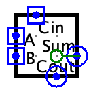
Take a look at the subcircuit 1-bit Adder. This 1-Bit (3,
2) Adder has three inputs, A, B,
and CarryIn. Its two outputs
are Sum and CarryOut. This
implementation is one of many possible. Although it may not look
exactly like what you saw in earlier courses, its functionality is
identical. Then examine this subcircuit's appearance:
Now create a 2-bit Ripple Adder subcircuit, that contains two instances of this 1-Bit Adder. This subcircuit has three inputs: A (2 bits), B (also 2 bits), and CarryIn (1 bit). Calculate the sum of A and B, and then collect the sum into a single 2-bit output Sum. Also add the output CarryOut (1 bit). You will need multiple splitters for this subcircuit.
Test your 2-bit Ripple Adder via the Poke tool, for a variety of inputs for A, B, and CarryIn.
In your proj1.txt file, calculate your gate propagation delays from when A, B, and CarryIn are set to when the final 2-bit Sum and the 1-bit CarryOut are calculated. When calculating your delays, treat each gate, regardless of type, as 1 delay unit. For example, a AND gate has 1 delay unit. If that same AND gate's top input is inverted, the top path has 2 delay units, while the bottom path's delay is still only 1 delay unit. Therefore, the AND gate's output has a propagation delay of 2 units.
Then create another new subcircuit, 4-Bit Adder, using two 2-Bit Ripple Adders. The inputs and outputs are similar as 2-Bit Adder, except the buses are now 4 bits wide. Furthermore, update proj1.txt. Calculate your gate propagation delays for your 4-Bit Adder.
As an additional challenge, and for extra credit, change this 4-Bit Adder to have a Carry Lookahead. See the Extra Credit section for details.
Part 2: Karnaugh Maps for 16-Bit ALU
The final project involves a 16-bit processor, so you will begin constructing your final project starting here.
The processor supports up to 32 operations. Four of those operations are listed below, along with their operation numbers:
- Addition (A + B): 1, 3, 7, 9, 11, 12, 13, 15, 23
- Subtraction (A - B): 5, 21
- Logical AND (A ∧ B): 2, 18
- Logical OR (A ∨ B): 0, 16
Calculate multiple Karnaugh maps, with each map corresponding to each of the above four operations. Each Karnaugh map has the five-bit input (i.e., operation number). When the output is 1, the ALU will perform the operation. Draw these Karnaugh maps as ASCII art, saved to proj1.txt. Alternatively, draw them on physical paper, take a snapshot, and upload the resulting images with the rest of your files. For each map, be sure to label the axes and calculate the sum of products. For each map, identify which operation it corresponds.
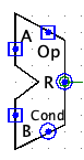
Part 3: 16-bit ALU
Now you will build a 16-bit ALU for your processor. Create a new subcircuit, 16-bit ALU. There are three inputs:
- A (16 bits)
- B (16 bits)
- Operation Number (5 bits)
- Result (16 bits)
- Condition Codes (4 bits)
Special Restriction: You may not use Logisim's built-in adder nor subtractor subcircuits for this part of the assignment.
Then add these 4 condition codes to your ALU:
- Z: Zero
- True when the result from the ALU is exactly zero.
- C: Carry
- True when the carry-out bit of the ALU's last adder unit is a one.
- N: Negative
- True if the ALU result is negative (i.e., MSB is 1).
- V: Overflow
- True if the ALU result's MSB does not match the operands.
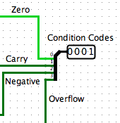
Calculate all four condition codes, regardless of the input operation number. Join the codes into a single 4-bit output pin. Label each bit position for ease of grading.
It is true that Carry and Overflow condition codes are only meaningful when the ALU operation is addition or subtraction. In other words, Carry and Overflow are Don't Care for non-addition and non-subtraction operations.
Consider updating your ALU's appearance. You will be reusing it
multiple times in this class. This is what the instructor uses:
Part 4: Roulette State Machine
The next task is to design the roulette game logic. Internally, the game has a state machine, with these four states:
- State 0: Get Bet
- In this state, the user bets on one of four numbers. The user may keep adjusting the bet. Once the player presses the Go button, the current bet is locked; also proceed to next state.
- State 1: Start Spin
- In this state, the circuit initializes the virtual roulette wheel. After one clock cycle, proceed to next state.
- State 2: Spinning
- In this state, the roulette wheel is spinning. When the wheel stops, proceed to next state.
- State 3: Payout
- Nothing happens in this state. After one clock cycle, proceed to State 0.
Examine the subcircuit Roulette SM. This subcircuit has three inputs:
- Go (1 bit)
- Done Spinning (1 bit)
- Clock (1 bit)
- Bet Light (1 bit)
- Spin Light (1 bit)
- State (2 bits)
First add a two-bit counter, State Counter. Connect Clock to State Counter. The counter only increments if any of these four conditions are true:
- State is 0 and Go is 1, or
- State is 1 or State is 3, or
- State is 2 and Done Spinning is 1
Send State Counter's output to the ouput State. When the counter is zero, output a 1 to Bet Light. For all other values, output a 1 instead to Spin Light.
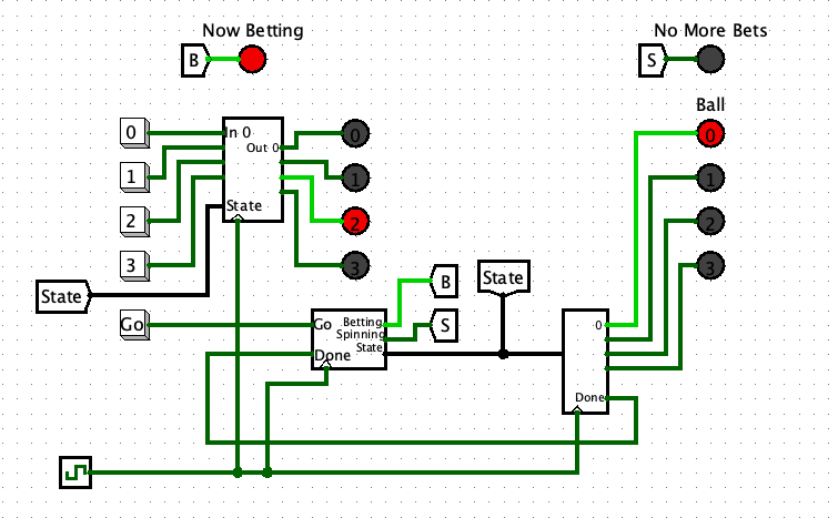
Part 5: Roulette Player and Roulette Ball
Examine the subcircuit Roulette Player. This subcircuit has six inputs:
- In 0 (1 bit)
- In 1 (1 bit)
- In 2 (1 bit)
- In 3 (1 bit)
- State (2 bits)
- Clock (1 bit)
- Out 0 (1 bit)
- Out 1 (1 bit)
- Out 2 (1 bit)
- Out 3 (1 bit)
First add a two-bit register, Player. Connect Clock to Player. The register's value is updated to 0, 1, 2, or 3 when In 0, In 1, In 2, or In 3 is 1 (respectively), but only when State is 0.
Decode Player's value, to output a 1 to Out 0, Out 1, Out 2, or Out 3.
Finally, examine the subcircuit Roulette Ball. This subcircuit has two inputs:
- State (2 bits)
- Clock (1 bit)
- Light 0 (1 bit)
- Light 1 (1 bit)
- Light 2 (1 bit)
- Light 3 (1 bit)
- Done Spinning (1 bit)
First add an eight-bit random generator, RNG. Then add an eight-bit register, Target. Then add an eight-bit counter, Ball. Connect Clock to RNG, Target, and Ball. Finally, add your ALU, from Part 3.
For all states, keep generating a new random value within RNG. When the state is 1, copy RNG into Target. When the state is 2, keep incrementing Ball, allowing that counter to rollover back to zero.
Decode the last two bits of Ball, outputting a 1 to Light 0, Light 1, Light 2, or Light 3. Output 1 to Done Spinning when Target and Ball are equal.
Special Restriction: You must use your ALU to calculate Done Spinning. You will find that you need to add more things to Roulette Ball.
Finally, test your overall Roulette. You ought not need to modify this subcircuit. To get the full casino experience, set the tick rate to about 64 hertz.
Other Hints and Notes
- Ask plenty of questions on the Blackboard discussion board.
- At the top of your proj1.txt file, list any help you received as well as web pages you consulted. Please do not use any URL shorteners, such as goo.gl or TinyURL. Also, do not cite shared data services, such as Pastebin, Dropbox, or Google Drive.
- Your proj1.txt should include: from Part 2 calculations of 2-Bit Adder's propagation gate delay, 4-Bit Adder's propagation gate delay; from Part 3 four Karnaugh maps and Sum of Products.
- Be sure to submit both proj1.circ and proj1.txt to receive full credit.
- You may modify all given subcircuits, as necessary.
- In this version of the project, nothing of interest occurs when State is 3.
Extra Credit
You may earn an additional 10% credit for this assignment by implementing a 4-Bit Carry Lookahead Adder. Use this Lookahead Adder for the 16-bit ALU. In addition, your gate propagation delay calculation should be for your Lookahead Adder, instead of a 4-Bit Ripple Adder.
If you choose to perform this extra credit, put a comment at the top of your proj1.txt, alerting the grader.