
Part II: Dividing Cubes Algorithm
Production of 3-D medical images involves two steps: surface reconstruction and surface display.
Shading method
Gradient shading is used here to improve the image quality by giving contrast that depends on the surface orientation. Since the gradient is perpendicular to surfaces of constant density, the gradient vector of the 3-D density function is used to calculate the surface normal. If the 3-D data from a rectangular lattice in space with a unit cell of dimensions a, b, and c, the gradient vector g = (gx, gy, gz) is calculated from the density function by taking central differences between the densities, f (x0, y0, z0), evaluated at the lattice point (x0, y0, z0)
| gx = [ f(x0 + a, y0, z0) – f ( x0 – a, y0, z0 )]/2a, | (1) | |
| gy = [ f(x0 + b, y0, z0) – f ( x0 – b, y0, z0 )/2b, | (2) | |
| gz = [ f(x0 + c, y0, z0) – f ( x0 – c, y0, z0 )/2c. | (3) |
To locate the surface, the density function is linearly interpolated in the space (x, y, z) between the lattice points (x0, y0, z0) and compared with the iso-surface value C of the desired surface. Thus the surface of interest is
| f (x0, y0, z0) = C. | (4) |
The gradient vector defined at each lattice point is trilinearly interpolated over the voxel to give a local value of the gradient vector, g, at the desired surface. The unit surface normal is the gradient normal divided by its magnitude, |g| [1].
Surface reconstruction
Dividing cubes algorithm was developed to eliminate the scan conversion step of polygonal display algorithm. In medical images there are many surface elements and the triangles created by the polygonal algorithm may occupy only a small area on the raster display. As the number of facet increases, the size of each triangle decreases and approaches the pixel size. For complex medical images, it is more efficient in memory and time to display point primitives on the raster display directly.
Figure 1. Point surface representation [9].
The dividing cubes algorithm subdivides the voxels into smaller cubes that lie on the surface of the object and projects the intensity calculated for each cube onto the viewing plane, forming a gradient shaded representation of the three-dimensional object Figure 1. The voxel scale is chosen to make the smaller cubes equal to the pixel size on the raster display. The display resolution, rather than the voxel size, limits the image resolution. By subdividing the voxel, we interpolate the data in three dimensions to approximate the continuous density function with a fine cubic lattice of integers. This subdivision increases the accuracy of the interpolation. However, the finer the subdivision, the more surface points need be processed. The densities at the corners of the small cubic element are calculated from eight voxel vertices by linear interpolation. The algorithm calculated an index for each voxel by comparing the cube vertices with the value of the desired surface as in the polygonal algorithm. Each cube is classified as being inside the surface, outside the surface or intersecting the surface. A cube inside a surface has eight cubically connected densities greater than the constant density of the surface, a cube outside the surface has eight densities less than the surface, and otherwise the cube intersects the surface. For those cubes that lie on the surface, we interpolate the gradient vector at each voxel vertex at the center of each surface cube to provide an estimate the surface normal vector. Both surface points and corresponding normal vectors are transformed and projected onto the viewing plane. OpenGL will take care of the removes of the hidden surface [1].
Dividing Cubes Algorithm [1, 9]
The dividing cubes algorithm includes the following steps:
The test data set for dividing cubes algorithm, 3dhead.new, is from the Chapel Hill Volume Rendering Test Data Set, Volume I. The head data is a 109-slice MRI data set of a human head. Complete slices are stored consecutively as a 256 x 256 array. Pixels consist of 2 consecutive bytes making one binary integer. Data taken on the Siemens Magnetom and provided courtesy of Siemens Medical Systems, Inc., Iselin, NJ.
The data set contains 256x256x109 data values; the minimum and maximum data values in the set are 2 and 4095. To choose an appropriate iso-surface value between 2 and 4095 will take considerable large amount of time, the data viewer from the first part of this project can release a lot of pain in the process of choosing a proper iso-surface value. We can, first, find the distribution and frequencies of the data values and preview the raw images. This will give you an idea what kind of tissue will fall in what range of the data values. Then, repeatedly selections of different range of values help narrow down the interval of possible iso-surface values for further testing. After an appropriate iso-surface value is chosen, we can use that value as the threshold value in the dividing cubes algorithm to generate the surface we are interested in studying.
This part of the project is also written in C, runs on a SGI workstation. The rendering of the images are also done by OpenGL. The pixel size is set to be 0.05 x 0.05 when displaying the images.
Using data viewer from the first part of this project to preview the data file, 3dhead.new, and to collect the information of different tissues falls on what range this information helps in choosing a specific surface constant to obtain the result desired. The result shown in figure 2 is produced by data viewer with the normalized data values fall between 0.1460 – 0.1462. There are 1233 of them with the iso-surface constant of 600, which is used in creating the images in figure 2.

Figure 2. The rough image from data viewer with the data falls between 0.1460 and 0.1462.
The results of the dividing cube algorithm show 3-D reconstruction at different voxel subdivisions and magnifications in figure 3.
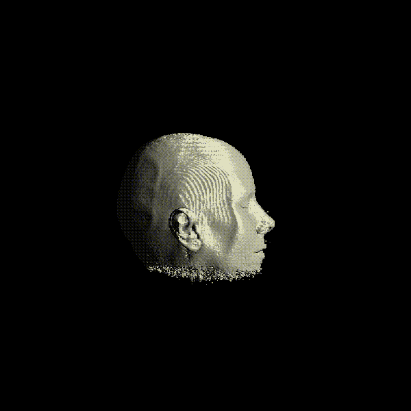
Figure 3. (a) The result of voxel subdivision into 2x2x2 cubes.
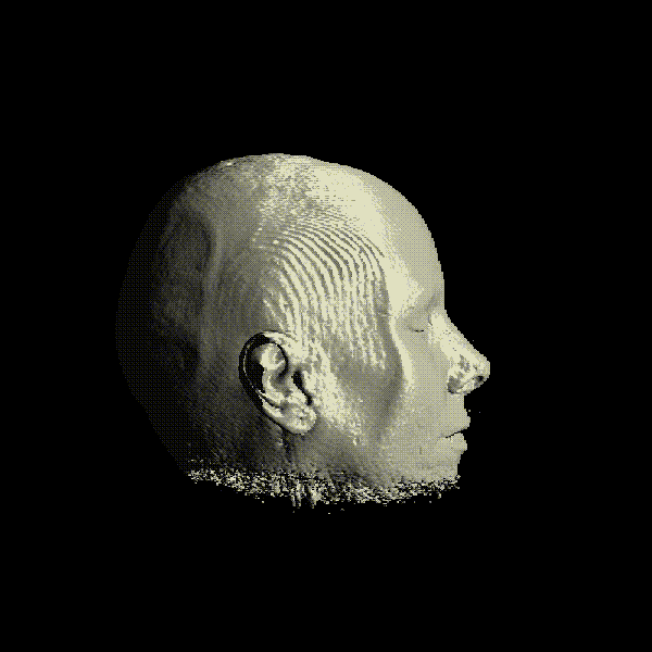
Figure 3. (b) The result of voxel subdivision into 3x3x3 cubes.
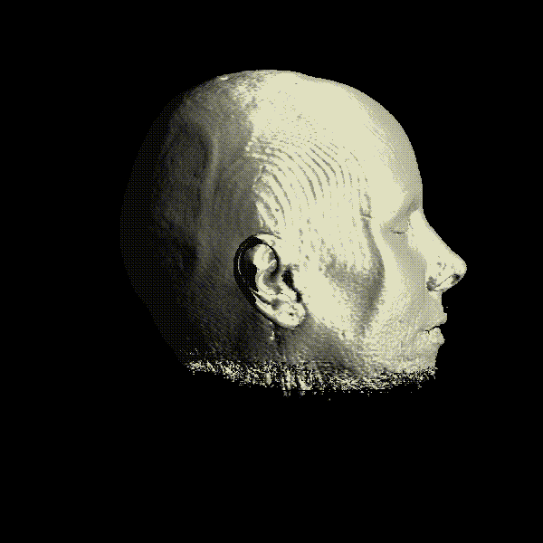
Figure 3. (c) The result of voxel subdivision into 4x4x4 cubes.
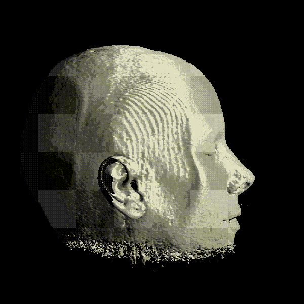
Figure 3. (d) The result of voxel subdivision into 5x5x5 cubes.