CMSC 435/634: Computer Graphics
Lab 5: 3D Perspective Viewing
Due November 15, 2000

Due November 15, 2000
Purpose:
To implement 3D perspective viewing transformations. This project involves implementation of 3D clipping, viewing transformations, and back face removal.
This lab will extend your previous work to 3D perspective viewing.
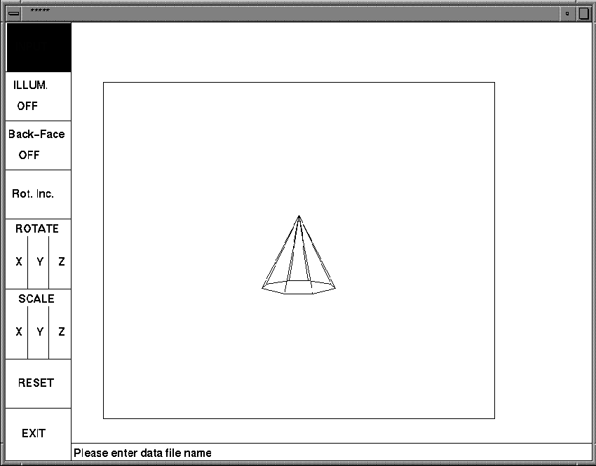
Your program should follow these specifications: When started, the program displays a window with menu buttons displayed on the bottom, looking something like the example in the figure, except that you need a "TRANSLATE XYZ button" and your buttons will be at the bottom.

When the user clicks the left mouse button on one of the menu buttons the following action will take place:
VRP VPN VUP COP hither yon window light
Where VRP VPN VUP COP and light are triplets of real numbers, window is a quadruple of real numbers corresponding toand hither and yon are one real number each. The light parameters will be used for extra credit. VPN and VUP are vectors and VRP and COP are points. ALL OF THEM ARE DEFINED IN TERMS OF THE XYZ COORDINATES, in which the object is defined. hither and yon are defined in terms of uvn coordinates (remember that hither and yon are offsets from the view plane in the n axis.) VPN corresponds to n axis and v is the projection of VUP onto the view plane. uvn forms a right-handed system. window is also defined in terms of the uvn coordinate and it lies in the view plane. window is defined relative to COP. Remember to normalize VPN for uvn computation.
An example input file is easy.dat:
/afs.umbc.edu/users/e/b/ebert/home/cs435/435_data/easy.det
0 0 0 0.0 0.0 1.0 0.0 1.0 0.0 0 0 50 0 -10 -2 2 -1 1 100.0 100.0 100.0
|-VRP-| |--VPN------| |--VUP----| |---COP-| hith yon |- window--| |------Light----|
The geometry file name has the following format:
DET_CODE (4 bytes)
num_pnts (n) (2 bytes short)
num_polys (m) (2 bytes short)
p1x p1y p1z (4 4
4 bytes float)
.....
pnx pny pnz (4 4 4 bytes float)
poly1-num_pnts (k) (2 bytes short)
poly1-pnt1 (2 bytes
short - array index begins at 1, i.e. pnts: 1 4 2)
...
poly1-pntk (2 bytes
short)
.....
polym-num_pnts (j) (2 bytes short)
polym-pnt1 (2 bytes
short)
....
polym-pntj (2 bytes
short)
An example for a cube is the following:
data 8 6
-0.5 0.5 0.5
0.5 0.5 0.5
0.5 -0.5 0.5
-0.5 -0.5 0.5
-0.5 0.5 -0.5
0.5 0.5 -0.5
0.5 -0.5 -0.5
-0.5 -0.5 -0.5
4 1 2 3 4
4 5 6 2 1
4 8 7 6 5
4 4 3 7 8
4 2 6 7 3
4 5 1 4 8
The program ~ebert/asc -a will print out a ".det" data file
for viewing as ascii
Sample input files are located in ~ebert/cs435/435_data/*.dat
A large number of binary data files, ".det", are located in
/usr/local/edge/data
Submit your assignment as 'lab5'. Your comments should include the environment (hardware and software) that you used to develop your program. To facilitate grading, your program should run properly on irix.gl, regardless of the system used for development. Include all necessary files and makefiles.