UMBC CMSC 313, Computer Organization & Assembly Language,
Spring 2002, Section 0101
DigSim Assignment 3: J-K Flip-Flops
Also available in PDF.
Due: Tuesday May 14, 2002
Objective
The objective of this assignment is to implement a finite state machine
using J-K flip-flops.
Assignment
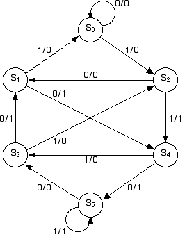
Consider the following transition diagram (from Contemporary
Logic Design, Randy H. Katz, Benjamin-Cummings Publishing,
1994) for a finite state machine with 1 input bit and 1 output bit:

Your assignment is to implement this finite state machine using J-K flip
flops. Assume that the state assignments are 000 for S0,
001 for S1, 010 S2, 011 for S3,
100 for S4, and 101 for S5.
- In the truth table below, let A, B and C be
the current states and A', B' and C' be the next states stored in
the J-K flip flops. (E.g., S4 is assigned A=1, B=0 and
C=0.) We also use D for the 1 bit input. Fill in the rest of the
truth table using the excitation table for J-K flip flops. For
example, in row 9, flip-flop A is currently storing 1 and must
store 0 in the next state. To achieve this, we look at the 10 entry
of the excitation table and note that the J input to flip-flop A
(call it JA) can be set to anything, but the K input, KA, must be
set to 1.
- Use the Karnaugh maps provided to simplify the Boolean
formulas for the J and K inputs to each J-K flip flop and for the
output value z.
- Implement the resulting circuit in DigSim.
Truth Table:
| |
A |
B |
C |
D |
A' |
B' |
C' |
z |
JA |
KA |
JB |
KB |
JC |
KC |
| 0 |
0 |
0 |
0 |
0 |
0 |
0 |
0 |
0 |
|
|
|
|
|
|
| 1 |
0 |
0 |
0 |
1 |
0 |
1 |
0 |
0 |
|
|
|
|
|
|
| 2 |
0 |
0 |
1 |
0 |
1 |
0 |
0 |
1 |
|
|
|
|
|
|
| 3 |
0 |
0 |
1 |
1 |
0 |
0 |
0 |
0 |
|
|
|
|
|
|
| 4 |
0 |
1 |
0 |
0 |
0 |
0 |
1 |
0 |
|
|
|
|
|
|
| 5 |
0 |
1 |
0 |
1 |
1 |
0 |
0 |
1 |
|
|
|
|
|
|
| 6 |
0 |
1 |
1 |
0 |
0 |
0 |
1 |
1 |
|
|
|
|
|
|
| 7 |
0 |
1 |
1 |
1 |
0 |
1 |
0 |
0 |
|
|
|
|
|
|
| 8 |
1 |
0 |
0 |
0 |
1 |
0 |
1 |
1 |
|
|
|
|
|
|
| 9 |
1 |
0 |
0 |
1 |
0 |
1 |
1 |
0 |
d |
1 |
|
|
|
|
| 10 |
1 |
0 |
1 |
0 |
0 |
1 |
1 |
0 |
|
|
|
|
|
|
| 11 |
1 |
0 |
1 |
1 |
1 |
0 |
1 |
1 |
|
|
|
|
|
|
| 12 |
1 |
1 |
0 |
0 |
d |
d |
d |
d |
d |
d |
d |
d |
d |
d |
| 13 |
1 |
1 |
0 |
1 |
d |
d |
d |
d |
d |
d |
d |
d |
d |
d |
| 14 |
1 |
1 |
1 |
0 |
d |
d |
d |
d |
d |
d |
d |
d |
d |
d |
| 15 |
1 |
1 |
1 |
1 |
d |
d |
d |
d |
d |
d |
d |
d |
d |
d |
Excitation Table for J-K Flip-Flops
| Q |
Q' |
J |
K |
| 0 |
0 |
0 |
d |
| 0 |
1 |
1 |
d |
| 1 |
0 |
d |
1 |
| 1 |
1 |
d |
0 |
Karnaugh maps are available in PDF.
Implementation Notes
- Consider the layout of your circuit with some care before
you start DigSim. You will have 6 wires for the 3 J-K flip-flops
going from one side of the circuit to another. Be sure to leave
room for this.
- Be sure to check your work carefully.
- Test your circuit and compare the transitions against the
original transition diagram.
Turning in your program
For this assignment you will turn in your work both on paper and
online. In class on Tuesday May14, turn in the truth table, the
Karnaugh maps and the resulting Boolean formulas on paper.
Save your circuit as you did in DigSim Assignment 1.
Submit the circuit file and the README file using the Unix submit
command as in previous assignments. The submission name for this
assignment is: digsim3.
Last Modified:
22 Jul 2024 11:29:37 EDT
by
Richard Chang
 to Spring 2002 CMSC 313 Section Homepage


 to Spring 2002 CMSC 313 Section Homepage